Oil Tank Level Sensor
Oil Tank Level Sensor
Accurate inventory management and operational safety in industrial environments depend heavily on the reliability of the oil tank level sensor. Whether managing crude oil in large storage terminals, diesel for backup generators, or lubricants in manufacturing plants, selecting the appropriate measurement technology is critical to preventing overfills, ensuring continuous supply, and maintaining environmental compliance.
As a professional manufacturer of industrial level measurement instruments, Welk provides a comprehensive range of solutions designed to handle the specific challenges of the oil and gas sector. From high-frequency radar to robust hydrostatic transmitters, understanding the underlying physics of these devices is the first step toward optimizing process automation. For more detailed technical specifications and product ranges, you can visit the Main Page of our product catalog.
Measurement Principles for Oil Level Sensing
Oil presents unique challenges for level measurement, including varying viscosities, low dielectric constants, and the presence of explosive vapors. Different technologies interact with these physical properties in distinct ways.
Radar Level Measurement (Non-Contact and Guided)
Radar technology is widely considered the gold standard for oil tank level sensor applications. It operates on the Time-of-Flight (ToF) principle.
* Non-Contact Radar: The sensor emits high-frequency microwave pulses (typically 26GHz or 80GHz). These pulses travel at the speed of light, reflect off the oil surface, and return to the sensor. The distance is calculated based on the travel time. Because microwaves do not require a medium, they are unaffected by vacuum, pressure, or temperature shifts in the tank headspace.
* Guided Wave Radar (GWR): This technology uses a physical probe (rod or cable) to guide the microwave pulse to the liquid surface. GWR is particularly effective for oils with very low dielectric constants ($ε_r$ between 1.4 and 2.0) because the probe concentrates the energy, ensuring a stronger return signal even when the surface reflectivity is poor.
Ultrasonic Level Sensors
Ultrasonic sensors also use the ToF principle but utilize sound waves instead of electromagnetic waves. The sensor sends a mechanical sound pulse that reflects off the liquid surface. While cost-effective, ultrasonic sensors are sensitive to the composition of the gas in the tank headspace. Since oil tanks often contain volatile organic compounds (VOCs) or heavy vapors, the speed of sound can vary, potentially leading to measurement errors unless temperature and gas compensation are applied.
Hydrostatic Pressure Transmitters
This method measures the liquid level by sensing the pressure exerted by the oil column at the bottom of the tank. The relationship is defined by the formula $P = ρgh$, where $P$ is pressure, $ρ$ is the density of the oil, $g$ is gravity, and $h$ is the height of the liquid. Hydrostatic sensors are highly reliable for vented tanks but require density compensation if the oil temperature changes significantly, as oil density is temperature-dependent.
Magnetic Level Gauges
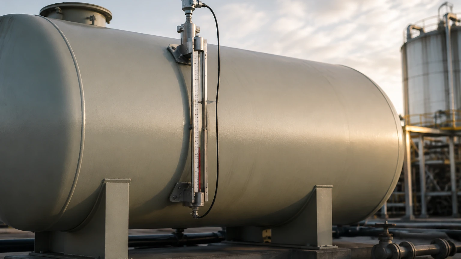
Magnetic gauges utilize a float containing a permanent magnet. As the oil level rises or falls, the float moves along a bypass chamber or within the tank, actuating a series of magnetic flags or a continuous transmitter. This provides a clear visual indication and a 4-20mA signal for remote monitoring, making it a favorite for high-pressure or high-temperature oil applications where electronic components must be kept away from the process media.
Technical Selection Criteria for Industrial Oil Storage
Selecting an oil tank level sensor requires a thorough evaluation of the application's physical and chemical parameters. Engineers should consider the following factors:
1. Dielectric Constant ($ε_r$): Most oils are non-conductive with low dielectric constants (typically 1.9 to 4.0). Non-contact radar sensors, especially 80GHz models, are preferred here because they can focus the beam to capture weak reflections. If the $ε_r$ is below 1.9, Guided Wave Radar is often the only viable electronic solution.
2. Tank Geometry and Obstructions: Internal structures like heating coils, ladders, or agitators can create false echoes for radar and ultrasonic sensors. Narrow-beam 80GHz radar is often used to bypass these obstructions.
3. Vapor and Condensation: In heavy oil or heated bitumen tanks, steam and oil vapors can condense on the sensor face. Sensors with PTFE-encapsulated antennas or air-purge systems are necessary to maintain signal integrity.
4. Hazardous Area Ratings: Due to the flammability of most oils, sensors must typically carry ATEX, IECEx, or UL certifications for Class I, Div 1 or Div 2 environments.
5. Viscosity and Coating: Heavy crude or waste oils can coat probes. In these cases, non-contact methods (Radar/Ultrasonic) are superior to contact methods (GWR/Float) to reduce maintenance requirements.
Comparison Table of Oil Level Sensing Technologies
| Technology | Accuracy | Best For | Limitations | Maintenance |
| :— | :— | :— | :— | :— |
| 80GHz Radar | ±1 mm | Large storage tanks, high precision | Higher initial cost | Very Low |
| Guided Wave Radar | ±2 mm | Small tanks, low dielectric oil | Subject to probe coating | Low |
| Ultrasonic | ±0.25% FS | Diesel, water-oil mix (vented) | Affected by foam and vapors | Medium |
| Hydrostatic | ±0.1% FS | Constant density lubricants | Requires density compensation | Medium |
| Magnetic Gauge | ±5 mm | High pressure/temp boilers | Mechanical wear of float | Medium |
Installation and Maintenance Best Practices
Proper installation is as important as selecting the right technology. When installing an oil tank level sensor, follow these engineering guidelines:
* Nozzle Positioning: For radar and ultrasonic sensors, avoid placing the sensor directly in the center of a domed tank, as this can concentrate false reflections. Also, ensure the sensor is not placed directly above the fill inlet to avoid turbulence and signal interference.
* Stilling Wells: In applications with heavy foam or extreme turbulence, installing the sensor inside a stilling well (a vertical pipe) can provide a calm surface for measurement. This is common in crude oil storage.
* Zero-Point Calibration: For hydrostatic sensors, the "zero" must be calibrated with the tank empty to account for the mounting height of the diaphragm relative to the tank bottom.
* Earthing and Surge Protection: Industrial oil tanks are often located outdoors. Ensure proper grounding and use surge protectors to prevent damage from lightning strikes or electrical transients.
Limitations and Troubleshooting
While modern sensors are highly advanced, they are not infallible. Common issues include:
* Signal Loss in Low Dielectric Media: If a radar sensor loses signal, it may be due to the oil's low reflectivity. Increasing the pulse frequency or switching to a guided wave system usually resolves this.
* Temperature Drift: Hydrostatic sensors may show fluctuating levels if the oil is heated or cooled without a temperature-compensated transmitter. This is because the volume changes while the mass (and thus the pressure) remains constant.
* Build-up on Probes: For contact-based sensors, paraffin or wax build-up can cause "level jumping." Regular cleaning or switching to non-contact radar is the standard solution for waxy crude oils.
Frequently Asked Questions (FAQ)
Q: Can I use an ultrasonic sensor for a gasoline tank?
A: It is generally not recommended. Gasoline produces heavy vapors that change the speed of sound, leading to significant inaccuracies. Furthermore, the risk of explosion requires high-level ATEX certification, which is more commonly found in radar units.
Q: How does viscosity affect the oil tank level sensor?
A: Viscosity primarily affects contact-type sensors. High-viscosity oil can stick to GWR probes or cause mechanical floats to move sluggishly. For high-viscosity media, non-contact radar is the most reliable choice.
Q: Is 80GHz radar better than 26GHz for oil?
A: Yes, in most cases. The 80GHz frequency allows for a smaller antenna and a much narrower beam angle (as low as 3 degrees). This helps in avoiding internal tank obstructions and provides a stronger reflection from low-dielectric oil surfaces.
Q: How do I measure the interface between oil and water?
A: Guided Wave Radar is the standard technology for interface measurement. It can detect the top of the oil layer and the point where the oil meets the water, provided the oil is non-conductive and the water is conductive.
Conclusion
Choosing the right oil tank level sensor involves balancing precision requirements with the physical realities of the storage environment. For most modern industrial applications, radar technology offers the best combination of accuracy and low maintenance. However, hydrostatic and magnetic solutions remain vital for specific high-pressure or cost-sensitive projects.
Welk continues to innovate in the field of industrial automation, providing customized OEM/ODM services to meet the global demand for reliable level measurement. To explore our full range of radar, ultrasonic, and hydrostatic instruments, please visit our Main Page for technical documentation and application support.