Pressure Gauge and Transmitter
Pressure Gauge and Transmitter
In the landscape of industrial automation and process control, the ability to monitor and manage pressure is fundamental. Whether in water treatment plants, chemical processing facilities, or oil and gas refineries, the choice between a pressure gauge and transmitter often dictates the efficiency, safety, and data-driven capabilities of the entire system. While both instruments serve the purpose of measuring the force exerted by a fluid or gas per unit area, their internal mechanisms, output formats, and application environments differ significantly. Understanding these nuances is essential for engineers and procurement professionals seeking to optimize their process loops.
Understanding Pressure Measurement Principles
Before selecting hardware, it is critical to understand the physics of how pressure is converted into a readable format. Pressure measurement is typically classified into three types: gauge pressure (referenced to atmospheric pressure), absolute pressure (referenced to a perfect vacuum), and differential pressure (the difference between two points in a system).
Mechanical Pressure Gauges
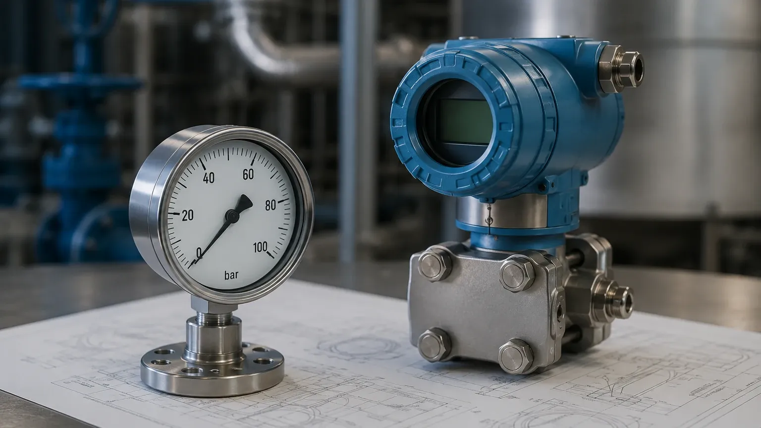
Mechanical pressure gauges rely on the physical deformation of a sensing element. The most common type is the Bourdon tube. This is a C-shaped, spiral, or helical tube that is closed at one end and connected to the process pressure at the other. As pressure increases, the tube tends to straighten. This mechanical movement is transmitted through a linkage and gear system to a pointer on a calibrated dial.
Another mechanical variant is the diaphragm gauge, which uses a flexible membrane. When pressure is applied, the diaphragm deflects, moving a pointer. Diaphragm gauges are particularly useful for low-pressure applications or when dealing with viscous or corrosive media that might clog a standard Bourdon tube.
Electronic Pressure Transmitters
A pressure transmitter (also known as a pressure transducer) converts the physical force into an electrical signal. This is achieved through several sensing technologies:
* Piezoresistive Sensors: These utilize the change in electrical resistance of a semiconductor (usually silicon) when subjected to mechanical strain. They are highly sensitive and compact.
* Capacitive Sensors: These measure the change in capacitance between a sensing diaphragm and a fixed plate. As pressure moves the diaphragm, the distance between the plates changes, altering the capacitance. These are known for their robustness and high accuracy in differential pressure applications.
* Strain Gauges: These involve bonding a fine wire or foil to a diaphragm. As the diaphragm deforms, the wire stretches, changing its resistance. This change is measured using a Wheatstone bridge circuit.
For a comprehensive overview of industrial sensing technology and to explore specific models, you can visit the Main Page of our technical catalog.
Pressure Gauge vs. Pressure Transmitter: Key Differences
The primary distinction between a pressure gauge and transmitter lies in how they communicate data. A gauge provides a local, visual indication, whereas a transmitter sends a signal to a remote control system (such as a PLC or SCADA).
| Feature | Pressure Gauge | Pressure Transmitter |
| :— | :— | :— |
| Output | Local visual dial | Electrical signal (4-20mA, 0-10V, HART) |
| Power Requirement | None (Mechanical) | Requires external power supply |
| Data Logging | Manual reading required | Continuous remote monitoring |
| Accuracy | Typically 0.5% to 2% of span | High accuracy (up to 0.05% of span) |
| Cost | Low to Moderate | Moderate to High |
| Maintenance | Calibration and physical inspection | Electronic calibration and diagnostic software |
| Environment | Limited by visibility and vibration | Can be installed in remote or hazardous areas |
Hydrostatic Level Measurement: The Role of Pressure Transmitters
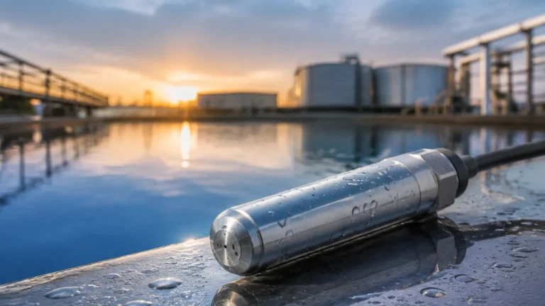
In many industrial contexts, especially those served by Welk, pressure instruments are used to determine the level of liquid in a tank. This is known as hydrostatic level measurement. The principle is based on the fact that the pressure at the bottom of a liquid column is proportional to the height of the liquid and its density.
The Formula:
$P = \rho \cdot g \cdot h$
Where:
* $P$ = Hydrostatic pressure (Pa or bar)
* $\rho$ (rho) = Density of the liquid ($kg/m^3$)
* $g$ = Gravitational acceleration (approx. $9.81 m/s^2$)
* $h$ = Height of the liquid (m)
A pressure transmitter installed at the base of an atmospheric (open) tank can accurately calculate the liquid level. For pressurized (closed) tanks, a differential pressure transmitter is required to subtract the top-side gas pressure from the total pressure at the bottom, ensuring only the liquid's weight is measured.
Selection Criteria for Industrial Applications
Choosing the right pressure gauge and transmitter requires a detailed evaluation of the process conditions. Engineers should consider the following factors:
1. Pressure Range: The operating pressure should ideally fall within the middle 50% to 75% of the instrument's full-scale range to ensure longevity and accuracy. Overpressure protection is also vital to prevent damage during process surges.
2. Media Compatibility: The wetted parts (the materials in contact with the fluid) must be chemically compatible. While Stainless Steel 316L is standard, aggressive chemicals may require Hastelloy, Monel, or PTFE coatings.
3. Temperature Limits: High-temperature processes can damage electronic components or cause thermal expansion in mechanical linkages. In such cases, cooling elements like siphons or capillary tubes with diaphragm seals are used to isolate the instrument from the heat.
4. Environmental Conditions: For outdoor installations, IP65 or IP67 ratings are necessary to protect against moisture and dust. In explosive atmospheres, intrinsically safe or explosion-proof certifications (ATEX/IECEx) are mandatory.
5. Output and Protocol: For transmitters, the choice between a simple 4-20mA analog signal and digital protocols like HART, Foundation Fieldbus, or Profibus depends on the complexity of the control system and the need for remote diagnostics.
Installation Guidelines and Best Practices
Proper installation is as important as the selection of the instrument itself. Incorrect mounting can lead to measurement errors or premature failure.
* Mounting Position: Transmitters should be mounted in a way that prevents gas bubbles from being trapped in liquid lines or liquid from condensing in gas lines. For liquid service, the transmitter is typically mounted below the tap point.
* Impulse Piping: The lines connecting the process to the instrument should be as short as possible to minimize lag. They should also be sloped (usually 1:12) to allow for self-draining or venting.
* Use of Manifolds: Installing a 3-way or 5-way valve manifold allows for the isolation of the instrument for calibration or maintenance without shutting down the entire process line.
* Vibration Dampening: If a pressure gauge is installed on a vibrating pump, use a liquid-filled (glycerin or silicone) gauge to dampen the pointer movement and lubricate the internal gears.
Common Challenges and Limitations
While highly reliable, a pressure gauge and transmitter setup can face several challenges:
* Density Variations: In hydrostatic level measurement, if the temperature of the liquid changes significantly, its density changes, which can lead to level errors. Modern smart transmitters can compensate for this if integrated with a temperature sensor.
* Clogging and Coating: In wastewater or slurry applications, the small orifices of pressure ports can clog. Using a flush diaphragm transmitter or a diaphragm seal with a large surface area can mitigate this risk.
* Ambient Pressure Changes: For very low-pressure measurements, changes in local barometric pressure can affect gauge pressure readings. Differential pressure sensors or absolute pressure sensors are preferred in these sensitive scenarios.
Frequently Asked Questions (FAQs)
Q: When should I use a pressure gauge instead of a transmitter?
A: Use a pressure gauge when you only need a local check for maintenance or safety (e.g., checking if a pipe is depressurized before opening it). Use a transmitter when the data needs to be sent to a control room, logged for compliance, or used to trigger alarms and automated valves.
Q: Can a pressure transmitter be used for vacuum measurement?
A: Yes, many transmitters are designed to measure compound pressure (both vacuum and positive pressure) or absolute pressure. Ensure the sensor is rated for the specific vacuum level required.
Q: How often should I calibrate my pressure instruments?
A: Calibration frequency depends on the criticality of the process and the stability of the instrument. Typically, industrial transmitters are calibrated annually, while gauges may be checked every 6 to 12 months. High-vibration or high-temperature environments may require more frequent checks.
Q: What is the benefit of a diaphragm seal?
A: A diaphragm seal protects the instrument from the process media. It is used when the media is corrosive, highly viscous, prone to solidifying, or when sanitary requirements (like in food processing) demand a flush surface that is easy to clean.
By carefully considering the measurement principles and application requirements, industrial operators can ensure they deploy the most effective pressure gauge and transmitter solutions for their specific needs. For further technical assistance and product selection, visiting the Main Page provides a direct path to expert support and high-performance instrumentation.