Pressure Level Sensor
Pressure Level Sensor
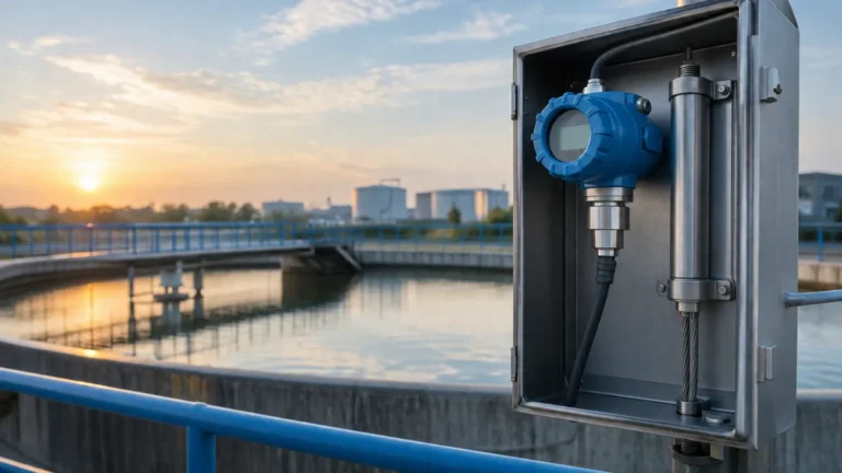
In industrial process control, the measurement of liquid levels is fundamental to ensuring operational safety, inventory management, and process efficiency. Among the various technologies available, the pressure level sensor—specifically the hydrostatic level transmitter—remains one of the most widely adopted solutions due to its reliability, versatility, and cost-effectiveness. By measuring the force exerted by a liquid column under gravity, these sensors provide accurate level data across diverse sectors, including water treatment, chemical processing, and oil and gas production.
This guide examines the engineering principles, selection criteria, and practical installation requirements for pressure-based level measurement to assist engineers and procurement specialists in identifying the optimal solution for their specific application requirements.
Understanding the Hydrostatic Principle
The operation of a pressure level sensor is based on the hydrostatic principle, which states that the pressure at a specific point in a static fluid is proportional to the weight of the liquid column above it. This relationship is mathematically expressed as:
P = ρ · g · h
Where:
* P is the hydrostatic pressure (typically measured in Pascals or bar).
* ρ (rho) is the density of the liquid (kg/m³).
* g is the local acceleration due to gravity (approximately 9.81 m/s²).
* h is the height of the liquid column (meters).
In a practical industrial setting, if the density of the liquid and the gravitational constant are known, the height (level) can be derived directly from the pressure reading. It is important to note that a standard pressure level sensor measures the "head pressure." In open tanks or vented vessels, the sensor must compensate for atmospheric pressure to ensure that only the pressure of the liquid column is recorded. This is usually achieved through a vented cable (for submersible models) or a reference port that exposes the back of the sensing diaphragm to the atmosphere.
Types of Pressure Level Sensors
Depending on the tank geometry and the nature of the media, different sensor configurations are required. Selecting the correct form factor is the first step in ensuring long-term performance.
1. Submersible Level Transmitters
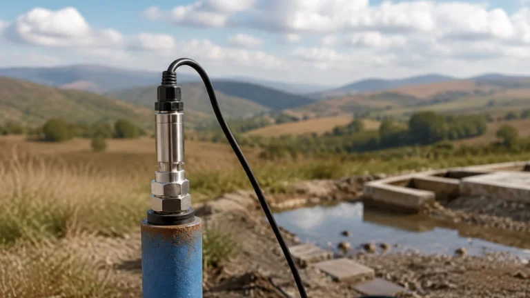
These sensors are designed to be lowered directly into the liquid. They consist of a sensing element housed in a waterproof casing (often 316L stainless steel or plastic for corrosive media) connected to a specialized cable. The cable contains a capillary vent tube that allows the sensor to compensate for changes in barometric pressure automatically. These are ideal for deep wells, reservoirs, and wastewater lift stations.
2. Externally Mounted (Threaded or Flanged) Sensors
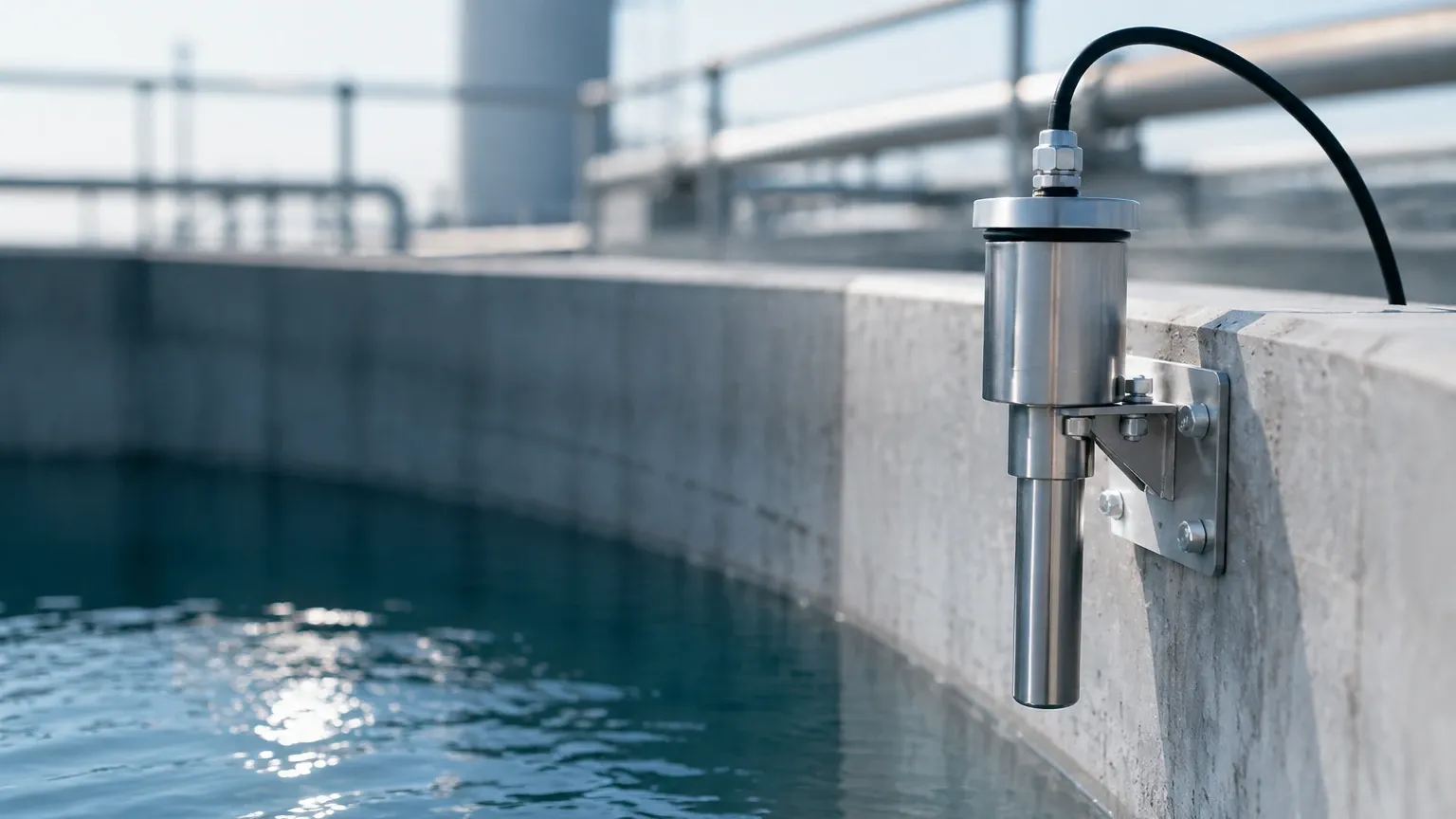
For tanks where internal access is restricted or where the liquid is agitated, sensors are mounted externally at the bottom or side of the vessel. These units use standard process connections, such as NPT threads or ANSI/DIN flanges. They are easier to maintain as they do not require the removal of a long cable from the top of the tank.
3. Differential Pressure (DP) Transmitters
In pressurized or sealed vessels, the air space above the liquid (the "ullage") may be under pressure or vacuum. A standard hydrostatic sensor would provide an incorrect reading because it cannot distinguish between liquid weight and gas pressure. A differential pressure level sensor solves this by measuring the pressure at both the bottom and the top of the tank. The device subtracts the top pressure from the bottom pressure, leaving only the hydrostatic pressure of the liquid.
Selection Criteria for Industrial Applications
Choosing a pressure level sensor requires a detailed analysis of the process environment. Engineers should consult the Main Page of technical documentation to verify compatibility with specific industrial standards.
Media Compatibility and Material Science
The chemical composition of the liquid determines the materials for the diaphragm and housing. While 316L stainless steel is the standard, aggressive chemicals like hydrochloric acid or seawater may require:
* Ceramic Diaphragms: Highly resistant to abrasion and many corrosive chemicals.
* Tantalum or Hastelloy: Used for extreme chemical resistance.
* PTFE/FEP Coatings: Often used for submersible cables in acidic environments.
Pressure and Temperature Ranges
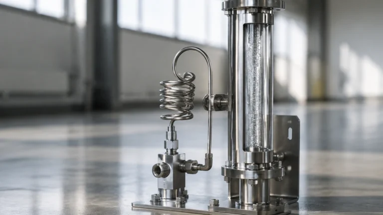
Sensors must be rated for the maximum possible head pressure and any potential pressure surges (water hammer). Temperature is equally critical; standard sensors typically operate up to 80°C (176°F). For high-temperature applications, such as boiler feed water or hot oil, cooling elements or remote capillaries are necessary to protect the sensitive electronics from thermal damage.
Accuracy and Output Signals
Most industrial applications utilize a 4-20mA analog signal, often with HART (Highway Addressable Remote Transducer) protocol for digital calibration and diagnostics. For integration into modern IoT or PLC systems, RS485 (Modbus) or Profibus outputs are also common. Accuracy is typically rated as a percentage of the Full Scale (FS), with standard industrial units offering ±0.5% FS and high-precision models reaching ±0.1% FS.
Selection Table: Pressure Level Sensor vs. Application
| Application | Recommended Sensor Type | Key Consideration |
| :— | :— | :— |
| Deep Groundwater Well | Submersible (Hydrostatic) | Requires high-tensile vented cable |
| Pressurized Chemical Tank | Differential Pressure (DP) | Must account for vapor pressure |
| Wastewater Sump | Non-clogging Submersible | Large diaphragm to prevent fouling |
| Food & Beverage Silo | Hygienic Flush Diaphragm | Must meet CIP/SIP requirements |
| Fuel Storage Tank | Intrinsically Safe Pressure Sensor | Explosion-proof (ATEX/IECEx) rating |
Installation and Maintenance Guidelines
Correct installation is paramount to preventing measurement drift and physical damage to the pressure level sensor.
Positioning and Mounting
* Avoid Turbulence: Sensors should not be installed directly near an inlet pipe or an agitator. The kinetic energy of moving fluid can create localized pressure fluctuations, leading to unstable readings. If turbulence is unavoidable, a stilling well (a perforated pipe) should be used to shield the sensor.
* Sediment Protection: In tanks where solids settle at the bottom, the sensor should be mounted slightly above the floor of the vessel to prevent the diaphragm from being buried in sludge.
* Venting: For submersible units, the vent tube in the cable must remain unobstructed. It should terminate in a dry environment, often using a desiccant bellows or a specialized junction box to prevent moisture from entering the tube and causing internal corrosion.
Calibration and Zeroing
Since the sensor measures the weight of the fluid, it must be zeroed in the actual environment. For example, if a sensor is mounted at the end of a long pipe extension, the "zero" point must account for the fluid trapped in that extension. Regular calibration checks are recommended every 12 to 24 months, depending on the criticality of the process.
Limitations and Mitigation Strategies
While highly reliable, the pressure level sensor has specific limitations that engineers must manage:
1. Density Sensitivity: Because the sensor measures weight, any change in liquid density will change the level reading even if the actual height remains the same. If a process involves fluids with varying densities (e.g., due to temperature changes or mixing of different chemicals), a temperature-compensated system or a secondary density measurement may be required.
2. Mechanical Damage: The sensing diaphragm is typically very thin (often less than 0.1 mm). It should never be touched with tools or fingers during installation. In applications with suspended solids, a protective cage or a flush-mount design is preferred.
3. Clogging: In viscous media like heavy crude oil or pulp and paper slurries, the pressure port can become blocked. Utilizing a flush diaphragm—where the sensing surface is level with the process connection—prevents material buildup.
Comparison with Alternative Technologies
To provide a comprehensive engineering reference, it is useful to compare pressure-based measurement with non-contact methods like Radar or Ultrasonic sensors.
* Pressure vs. Ultrasonic: Ultrasonic sensors can be affected by foam, heavy vapors, or dust in the air space. A pressure level sensor is unaffected by surface conditions, making it superior for foaming liquids.
* Pressure vs. Radar: Radar is highly accurate and non-contact, but it is significantly more expensive. For standard water or oil tanks where contact with the media is acceptable, a pressure level sensor offers a more cost-effective solution with comparable reliability.
* Pressure vs. Float Switches: Float switches provide point-level detection (on/off), whereas pressure sensors provide continuous level monitoring, allowing for better pump control and inventory tracking.
Frequently Asked Questions
Q: Can I use a pressure level sensor for a tank that is under vacuum?
A: Yes, but you must use a differential pressure (DP) transmitter. A standard gauge pressure sensor will provide an incorrect reading because the vacuum will pull on the diaphragm, simulating a lower liquid level than what actually exists.
Q: How long can the cable be for a submersible sensor?
A: Cables can often extend up to 500 meters or more. However, for very long runs, signal degradation and the weight of the cable must be considered. In these cases, a 4-20mA signal is preferred over voltage-based signals to ensure data integrity over the distance.
Q: What happens if the vent tube gets wet?
A: If moisture enters the vent tube, it can lead to two problems: it may block the tube, preventing atmospheric compensation, or it may reach the internal electronics, causing a permanent short circuit. Always use a moisture-protected junction box.
Q: Is the sensor affected by the shape of the tank?
A: No. The hydrostatic pressure depends only on the vertical height of the liquid, not the volume or the width of the tank. A pressure level sensor will read the same at the bottom of a 10-meter deep narrow pipe as it will at the bottom of a 10-meter deep wide lake.
Conclusion
The pressure level sensor remains a cornerstone of industrial instrumentation due to its simplicity and robust performance. By understanding the hydrostatic principle and carefully selecting materials and mounting configurations, operators can achieve high-precision measurements even in challenging environments. For those seeking specific product specifications or application support, reviewing the comprehensive range of industrial instruments on the Main Page is the recommended next step in the engineering process. Proper attention to density variations and atmospheric venting will ensure that the chosen sensor provides reliable data throughout its service life.