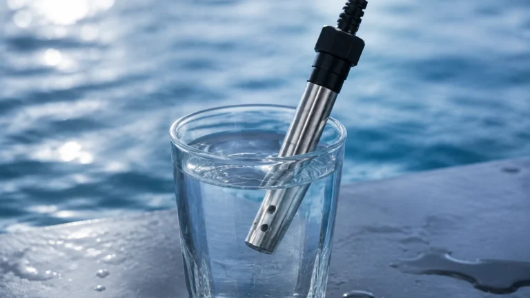
Promag 53
Promag 53
In the landscape of industrial process automation, electromagnetic flow measurement stands as one of the most versatile and reliable methods for monitoring conductive liquids. The Promag 53 represents a high-performance transmitter within this category, designed to handle complex tasks that go beyond simple flow rate indication. While often discussed in the context of flow, its role is deeply interconnected with total process control, including inventory management and tank monitoring systems commonly supported by level measurement instrumentation.
For engineers and plant managers, understanding the technical nuances of the Promag 53 is essential for ensuring system accuracy, especially when integrating flow data with level readings from radar or ultrasonic sensors. This guide provides a factual, engineering-focused overview of the technology, its application, and its integration into broader industrial frameworks.
Measurement Principle: Faraday’s Law of Induction
The Promag 53 operates on the physical principle of Faraday’s Law of Induction. To understand its application, one must first grasp how a magnetic field interacts with a moving conductive fluid.
When a conductive liquid flows through a pipe, it passes through a magnetic field generated by two field coils located on the flow sensor. According to Faraday’s Law, a voltage is induced within the liquid. This induced voltage ($U_e$) is directly proportional to the flow velocity ($v$), the magnetic field strength ($B$), and the distance between the electrodes ($d$), which corresponds to the pipe diameter. The formula is expressed as:
$$U_e = B \cdot v \cdot d$$
In this equation, the magnetic field strength and the electrode distance are constant. Consequently, the induced voltage is a linear function of the flow velocity. The Promag 53 transmitter converts this voltage signal into a standardized output (such as 4-20 mA or a digital bus signal). Because the measurement depends on the cross-sectional area of the pipe, the volumetric flow rate can be calculated with high precision.
Key Advantages of the Principle
* No Pressure Loss: The sensor is a straight-through tube with no moving parts or obstructions.
* Independence from Fluid Properties: Measurement is generally unaffected by viscosity, density, temperature, or pressure, provided the liquid meets the minimum conductivity requirement (typically > 5 μS/cm).
* Bi-directional Measurement: The technology inherently supports measuring flow in both directions.
Technical Capabilities of the Promag 53 Transmitter
The Promag 53 is the high-end transmitter variant, distinguished from more basic models by its advanced signal processing and user interface. It is designed for applications requiring high functionality, such as batching, cleaning-in-place (CIP) monitoring, and complex data logging.
Advanced Diagnostics and Control
The transmitter features a multi-line backlit display and touch-control elements, allowing operators to configure the device without opening the housing—a critical feature in hazardous or wash-down environments. It supports various software packages for specific functions:
1. Batching: Integrated control for filling and dosing applications.
2. Electrode Cleaning: High-frequency cleaning cycles to prevent build-up on electrodes in wastewater or chemical applications.
3. Advanced Diagnostics: Continuous monitoring of the measuring circuit and sensor integrity.
Communication Protocols
To facilitate integration into modern Distributed Control Systems (DCS) and Programmable Logic Controllers (PLC), the Promag 53 supports a wide array of communication standards:
* HART
* PROFIBUS DP/PA
* FOUNDATION Fieldbus
* MODBUS RS485
* EtherNet/IP
Selection Criteria and Material Compatibility
Selecting the correct sensor to pair with a Promag 53 transmitter requires a detailed analysis of the process media. The internal liner and the electrodes must withstand the chemical and physical properties of the fluid.
Liner Materials
| Liner Material | Temperature Range | Typical Applications |
| :— | :— | :— |
| PFA | -20°C to +180°C | Highly corrosive chemicals, food and beverage (hygienic). |
| PTFE | -40°C to +130°C | Strong acids and bases, industrial chemicals. |
| Polyurethane | -20°C to +50°C | Water, abrasive slurries, wastewater. |
| Hard Rubber | 0°C to +80°C | General water treatment, large diameter pipes. |
Electrode Materials
Electrodes are the interface between the fluid and the electronics. Common materials include Stainless Steel (1.4435/316L), Hastelloy C22, Tantalum, and Platinum. The choice depends entirely on the chemical compatibility with the process fluid to prevent corrosion or scaling.
Installation Considerations
To maintain the specified accuracy (often ±0.2% to ±0.5% of the measured value), strict adherence to installation guidelines is mandatory. Electromagnetic flowmeters are sensitive to flow profile disturbances and air entrapment.
Orientation and Piping
* Vertical Installation: The preferred orientation is in a vertical pipe with the flow moving upwards. This ensures the pipe remains full and prevents the accumulation of solids or air bubbles.
* Horizontal Installation: If installed horizontally, the electrode axis must be horizontal. This prevents air bubbles at the top of the pipe or sediment at the bottom from interfering with the signal.
* Inlet and Outlet Runs: To stabilize the flow profile, a straight inlet run of at least 5 x DN (nominal diameter) and an outlet run of 2 x DN is typically required. If there are significant disturbances like pumps or T-junctions, longer inlet runs may be necessary.
Grounding
Grounding is the most critical aspect of electromagnetic flowmeter installation. Since the induced voltage is often in the millivolt range, any stray electrical currents in the piping can cause significant errors. The liquid, the sensor, and the transmitter must be at the same electrical potential. This is achieved through grounding electrodes or grounding rings, depending on whether the piping is conductive or insulated (e.g., plastic or lined pipes).

Integration with Level Measurement Systems
In many industrial applications, flow measurement and level measurement are used in tandem to provide a complete picture of the process. For instance, in a chemical storage tank, a radar level meter provides the primary inventory data, while a Promag 53 on the inlet and outlet lines provides real-time mass balance data.
By comparing the integrated flow (totalizer) with the change in tank level, operators can:
* Detect Leaks: Discrepancies between flow-out and level-drop can indicate a leak in the tank or downstream piping.
* Verify Accuracy: Cross-referencing flow and level data allows for the field verification of both instruments.
* Optimize Dosing: In water treatment, flow rates dictate the dosing levels of chemicals, while level sensors ensure the dosing tanks are adequately supplied.
For comprehensive solutions in industrial automation, engineers often refer to the Main Page of specialized manufacturers to select the appropriate level sensors that complement their flow measurement strategy.
Limitations and Common Risks
While the Promag 53 is robust, it is not suitable for all applications. Engineers must be aware of the following limitations:
1. Non-Conductive Fluids: It cannot measure hydrocarbons (oils, fuels), distilled water, or gases.
2. Vacuum Conditions: Certain liners, particularly PTFE, can collapse or be damaged under vacuum conditions if not specifically designed with a supporting mesh.
3. Partially Filled Pipes: The meter will provide inaccurate readings if the pipe is not 100% full. In drainage or gravity-fed systems, specialized sensors for partially filled pipes must be used.
4. Coating and Scaling: If the process fluid tends to leave deposits, the electrodes can become insulated, leading to signal loss. Regular maintenance or the use of the transmitter's electrode cleaning functions is required.
Frequently Asked Questions (FAQ)
Q: What is the minimum conductivity required for the Promag 53?
A: Most applications require a minimum conductivity of 5 μS/cm. For demineralized water, special considerations or alternative technologies (like ultrasonic) may be needed.
Q: Can the Promag 53 be used for steam measurement?
A: No. Electromagnetic flowmeters only work with conductive liquids. For steam, vortex or differential pressure flowmeters are the standard choice.
Q: How often does the device need calibration?
A: Calibration frequency depends on the industry and the criticality of the measurement. In regulated industries like pharmaceuticals, annual calibration is common. In general water applications, the device may go several years without requiring recalibration, provided there is no electrode coating or liner wear.
Q: What happens if the pipe is not full?
A: The meter will likely over-read or provide an unstable signal. The Promag 53 includes an "Empty Pipe Detection" (EPD) feature that can trigger an alarm or force the output to zero when the pipe is not full, preventing false totals.
Conclusion
The Promag 53 transmitter is a cornerstone of modern flow measurement, offering the precision and communication capabilities required for complex industrial processes. By understanding the underlying physics, selecting the appropriate materials, and following rigorous installation standards, process engineers can ensure long-term reliability. When paired with high-quality level measurement instruments, these flowmeters form the backbone of efficient, safe, and accurate industrial automation systems.