Thermometer Well
Thermometer Well
In industrial process control, protecting sensitive instrumentation is as critical as the measurement itself. A thermometer well, commonly referred to as a thermowell, is a cylindrical fitting designed to protect temperature sensors—such as thermocouples, RTDs (Resistance Temperature Detectors), and bimetal thermometers—from the harsh conditions within a process vessel or pipeline. By acting as a barrier against high pressures, corrosive chemicals, and high-velocity fluid flow, thermowells ensure the longevity of the sensor while allowing for maintenance without depressurizing the system.
While Welk specializes in advanced level measurement solutions, including radar and ultrasonic sensors, temperature monitoring often serves as a critical secondary variable in many of the same tanks and reactors. Understanding the engineering principles behind thermometer wells is essential for any professional involved in process automation and fluid handling.
Measurement Principles and the Role of Thermowells
The primary function of a thermometer well is to provide a pressure-tight housing for a temperature sensor. However, introducing a physical barrier between the process medium and the sensor affects the measurement dynamics.
Heat Transfer Mechanism
Thermowells operate on the principle of thermal conduction. Heat from the process fluid must pass through the walls of the thermowell and the internal air gap (or thermal paste) to reach the sensing element. This creates a "thermal lag," meaning the sensor will respond more slowly to temperature changes than if it were directly immersed in the fluid. To minimize this lag, engineers must optimize the wall thickness and ensure the sensor tip is in direct contact with the bottom of the thermowell bore.
Pressure and Flow Dynamics
Beyond heat transfer, a thermometer well must withstand the mechanical stresses of the environment. In high-velocity pipelines, the fluid flowing past the well creates a phenomenon known as von Kármán vortex shedding. This creates periodic wake frequencies that can cause the well to vibrate. If the wake frequency matches the natural frequency of the thermowell, it can lead to mechanical resonance and eventual fatigue failure. Calculating these limits is a standard part of the selection process, typically following the ASME PTC 19.3 TW standard.
Types of Thermometer Wells and Selection Criteria
Selecting the correct thermowell requires balancing thermal response time with mechanical strength. The choice is largely dictated by the mounting method, the process pressure, and the nature of the fluid.
Stem Designs
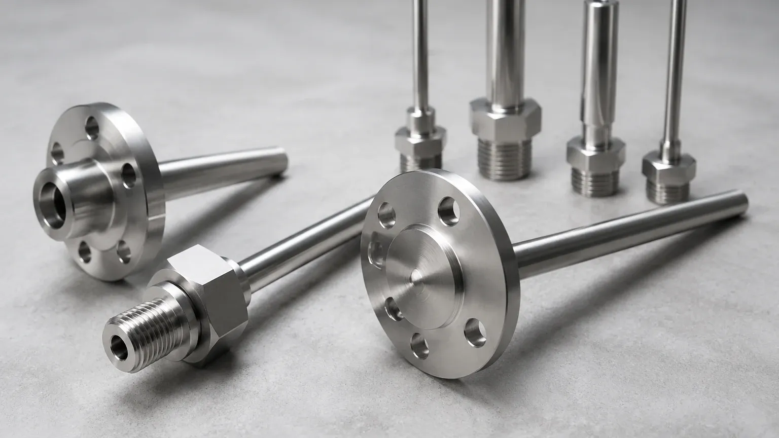
1. Straight Thermowells: The diameter is consistent along the entire insertion length. These are robust and easy to manufacture but have a slower thermal response due to the larger mass at the tip.
2. Stepped Thermowells: The diameter is reduced at the tip (e.g., from 19 mm to 12.7 mm). This reduces the thermal mass at the sensing point, significantly improving response time while maintaining strength at the base.
3. Tapered Thermowells: The diameter gradually decreases from the base to the tip. This design offers the best compromise between high structural rigidity (to resist flow-induced vibration) and a relatively fast response time.
Connection Types
The following table outlines the common mounting configurations used in B2B industrial applications:
| Connection Type | Mounting Method | Pressure Suitability | Typical Applications |
| :— | :— | :— | :— |
| Threaded | Screwed into a NPT or BSPT fitting | Low to Medium (< 150 bar / 2175 PSI) | Water treatment, HVAC, small-scale chemical piping. |
| Flanged | Bolted to a mating flange on the vessel | High (Limited by flange rating) | Oil and gas, large reactors, corrosive environments. |
| Socket Weld | Welded into a prepared pipe socket | Very High | High-pressure steam, permanent installations where leaks are prohibited. |
| Weld-in | Directly welded into the pipe or vessel wall | Highest | Power plants, high-pressure hydraulic systems. |
Material Selection and Chemical Compatibility
The material of the thermometer well must be compatible with the process medium to prevent corrosion and contamination. Since these components are often installed in the same environments as level measurement instruments, the material choice often mirrors that of the level sensor's wetted parts.
* Stainless Steel (304/316): The industry standard for water treatment and general chemical applications. 316L is preferred for its superior resistance to pitting corrosion.
* Hastelloy C-276: Used in highly aggressive environments involving strong acids, chlorides, or sour gas (H2S).
* Monel 400: Excellent for seawater applications and hydrofluoric acid service.
* Inconel 600: Suitable for high-temperature applications, often exceeding 1000°C (1832°F).
* PTFE/PFA Coating: For highly corrosive chemical storage tanks where metal contact must be avoided, a fluoropolymer coating can be applied to a stainless steel base.
Installation Guidelines and Best Practices
Proper installation is vital to ensure both measurement accuracy and the structural integrity of the thermowell. Engineers should consider the following factors during the design phase:
Insertion Length (U-Length)
To avoid errors caused by ambient heat conduction through the well's head (stem effect), the thermowell must be inserted deep enough into the process. A general rule of thumb for liquids is an insertion length equal to the sensor's diameter plus 50 mm (2 inches). For gases, the length should be significantly longer due to lower heat transfer coefficients.
Orientation
In pipelines, thermometer wells should ideally be installed at an elbow or at an angle pointing against the flow. This increases the surface area exposed to the fluid and ensures the tip is positioned in the center of the pipe where the temperature is most representative of the bulk fluid.
Bore Fit
The internal diameter (bore) of the thermowell should be only slightly larger than the outside diameter of the sensor. A gap larger than 0.25 mm (0.01 inches) can significantly increase response time. In some cases, a thermal conductive fluid or spring-loaded sensor is used to maintain contact with the bottom of the well.
Limitations and Maintenance
While thermometer wells are essential for protection, they are not without limitations.
1. Thermal Lag: As mentioned, the response time is slower. This may be problematic in processes with rapid temperature fluctuations that require high-speed PID control.
2. Maintenance Requirements: Over time, process media can build up on the exterior of the thermowell (scaling or fouling). This acts as an insulator, further slowing the response time and potentially causing measurement errors. Regular inspection and cleaning are necessary, especially in wastewater or heavy oil applications.
3. Vibration Risk: If the process flow velocity increases beyond the original design specifications, the thermowell may be at risk of failure due to wake frequency resonance. Any changes to pump capacity or pipe diameter should trigger a re-evaluation of the thermowell's mechanical limits.
Integration with Level Measurement Systems
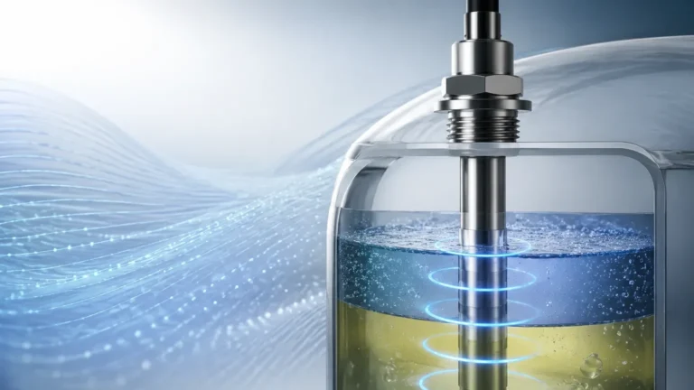
In modern industrial automation, temperature and level data are frequently integrated. For example, when measuring the volume of chemicals in a tank using a radar level meter, the density of the liquid changes with temperature. By installing a thermometer well alongside the level sensor, the control system can perform real-time temperature compensation, ensuring highly accurate volume calculations.
Welk provides the robust level sensing hardware required for these integrated systems, while the thermometer well ensures that the temperature data remains reliable and the sensors remain protected. For more information on selecting the right instrumentation for your facility, you can Review product options and application support.
Frequently Asked Questions (FAQs)
Q: How do I determine the maximum pressure a thermowell can handle?
A: The pressure rating depends on the material, the temperature, and the U-length. Manufacturers provide pressure-temperature rating charts. Generally, flanged and weld-in types offer the highest pressure ratings.
Q: What is the difference between a thermowell and a protection tube?
A: A thermowell is typically machined from solid bar stock and is designed for high-pressure applications. A protection tube is usually made from welded pipe or ceramic and is used for low-pressure, high-temperature applications like furnace exhausts.
Q: Can I use a thermometer well in a sanitary application?
A: Yes, but it must be a specialized sanitary thermowell. These are typically made from 316L stainless steel with a high-polish finish (Ra < 0.8 µm) and use Tri-Clamp connections to prevent bacterial growth in crevices.
Q: Is it necessary to use a lagging extension?
A: A lagging extension (T-length) is used when the pipe or vessel is insulated. It extends the head of the thermowell beyond the insulation layer, allowing for easy access to the sensor wiring without damaging the insulation.