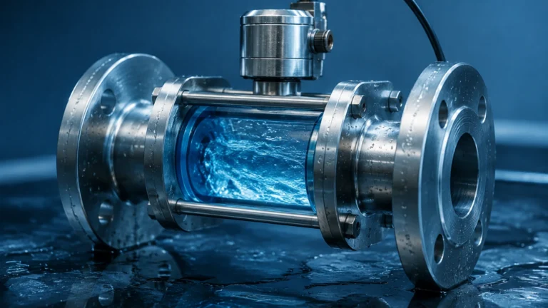
Transformer Rtd
Transformer Rtd
In the field of power distribution and industrial automation, the thermal management of transformers is a critical factor in ensuring operational longevity and grid stability. A transformer rtd (Resistance Temperature Detector) serves as the primary sensory component for monitoring the internal temperatures of these high-value assets. By providing precise, real-time data on winding and oil temperatures, these sensors allow for effective cooling control and provide early warnings against thermal degradation.
For engineers and plant managers, understanding the technical nuances of RTD technology is essential for selecting the right instrumentation to protect power infrastructure. This guide explores the measurement principles, selection criteria, and installation best practices for transformer rtd applications, while also examining how temperature data integrates with other critical parameters like fluid level.
Measurement Principles of Transformer RTDs
The operation of a transformer rtd is based on the predictable relationship between the electrical resistance of a metal and its temperature. This physical phenomenon, known as the temperature coefficient of resistance (TCR), dictates that as the temperature of a metal increases, its resistance to electrical flow also increases in a linear and repeatable manner.
Material Selection
While various metals exhibit resistance changes, platinum is the industry standard for transformer applications due to its chemical inertness, wide temperature range, and high degree of linearity. These sensors are typically categorized by their resistance at 0°C:
* Pt100: The most common type, featuring a resistance of 100 ohms at 0°C.
* Pt1000: Offers a resistance of 1000 ohms at 0°C, providing higher resolution and reduced sensitivity to lead wire resistance in certain configurations.
Resistance to Temperature Conversion
To convert the measured resistance back into a temperature value, industrial controllers use the Callendar-Van Dusen equation. In the context of a power transformer, where temperatures typically range from -40°C to +200°C, the RTD provides a level of accuracy (often within ±0.1°C to ±0.3°C) that far exceeds that of thermocouples or thermistors.
Wiring Configurations
Since the lead wires connecting the RTD to the monitoring equipment also possess resistance, various wiring schemes are employed to maintain accuracy:
1. 2-Wire: Simple but prone to errors caused by lead resistance; rarely used in critical transformer monitoring.
2. 3-Wire: The industrial standard. It uses a third wire to measure and subtract the lead resistance from the total circuit resistance, ensuring the output reflects only the sensor's temperature.
3. 4-Wire: Provides the highest precision by completely isolating the current source from the voltage measurement, typically reserved for laboratory calibration or extremely sensitive winding hot-spot monitoring.
Types and Applications in Power Transformers
Transformers require temperature monitoring at different locations to provide a complete picture of thermal health. A transformer rtd is usually deployed in one of three primary capacities:
Top Oil Temperature (TOT) Monitoring
RTDs are inserted into a thermowell (or pocket) located in the top layer of the transformer oil. This measurement indicates the overall thermal load of the transformer and is used to trigger cooling fans or pumps.
Winding Temperature Monitoring (WTI)
Directly measuring the temperature of a high-voltage winding is challenging due to insulation and potential issues. Instead, a transformer rtd is often used in a "thermal image" system. The sensor is placed in a well surrounded by a heating element proportional to the load current, simulating the temperature of the hottest part of the winding (the "hot spot").
Ambient Temperature Monitoring
External RTDs measure the surrounding air temperature. This data is compared with internal temperatures to calculate the thermal gradient, helping to determine if the cooling system is operating efficiently or if internal fouling is occurring.
Selection Criteria for Transformer RTDs
When specifying a transformer rtd, engineers must look beyond basic temperature ranges. The following table outlines the key evaluation criteria for industrial-grade sensors:
| Feature | Specification Requirement | Importance |
| :— | :— | :— |
| Sensor Element | Pt100 (Class A or 1/3 DIN) | Ensures high accuracy and interchangeability without recalibration. |
| Sheath Material | Stainless Steel (316L) | Provides corrosion resistance against transformer oils and environmental moisture. |
| Insulation Resistance | >100 MΩ at 500V DC | Prevents electrical interference from the transformer's electromagnetic field. |
| Vibration Resistance | Up to 10g (50-2000Hz) | Essential for sensors mounted on vibrating transformer tanks or near cooling fans. |
| Response Time (t90) | <10 seconds in moving oil | Ensures the control system can react quickly to sudden load changes. |
| Connection Head | IP67 or IP68 Rated | Protects wiring from rain, dust, and oil leaks in outdoor substations. |
Installation Considerations and Best Practices
The accuracy of a transformer rtd is heavily dependent on how it is installed. Poor thermal contact or improper positioning can lead to "temperature lag" or false readings.
Thermowell Integration
RTDs should never be in direct contact with the oil if the system requires maintenance without draining the tank. Instead, they are housed in thermowells. To ensure accurate heat transfer, the gap between the RTD probe and the thermowell wall should be filled with a high-conductivity thermal paste. The immersion length must be sufficient to ensure the sensing tip is fully submerged in the active oil flow, typically at least 150mm to 200mm depending on the tank size.
Electromagnetic Interference (EMI) Shielding
Transformers are high-EMI environments. RTD signal cables must be shielded and twisted to prevent induced voltages from distorting the temperature reading. The shield should be grounded at one end (usually at the controller) to avoid ground loops.
Sealing and Gaskets
For sensors mounted on the tank wall or cover, high-quality Nitrile or Viton gaskets are required to prevent oil leaks. Over time, thermal cycling can cause seals to degrade, so regular inspection of the entry points is necessary.
Integration with Level Measurement Systems
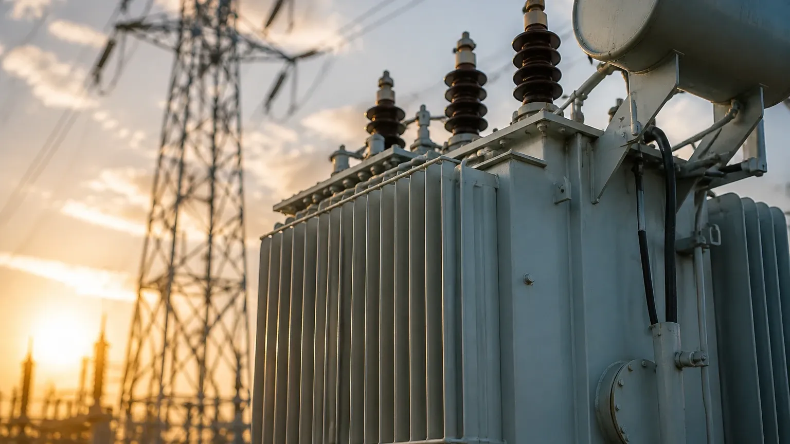
In practical engineering, temperature monitoring is rarely performed in isolation. There is a direct physical relationship between the temperature measured by a transformer rtd and the oil level within the conservator tank. As oil temperature rises, the fluid expands, causing the level to rise. Conversely, cooling leads to contraction and a drop in level.
By cross-referencing data from the Main Page of a monitoring system—which might include magnetic level gauges or hydrostatic transmitters—operators can perform a mass balance check. If the RTD indicates a high temperature but the level meter shows a decreasing oil level, this is a definitive indicator of a leak rather than standard thermal contraction. This integrated approach is a cornerstone of modern transformer asset management.
Limitations and Potential Risks
While RTDs are highly reliable, they are not immune to failure. Engineers should be aware of the following risks:
* Mechanical Stress: Constant vibration from the transformer core can lead to work hardening of the internal platinum wires, eventually causing an open-circuit failure.
* Self-Heating: If the excitation current supplied by the controller is too high, the RTD will generate its own heat, leading to an artificially high temperature reading. Currents should typically be kept below 1mA.
* Drift: Although minimal compared to other sensors, RTDs can experience slight calibration drift over years of exposure to extreme thermal cycling. Periodic verification against a reference standard is recommended.
* Moisture Ingress: If the connection head is not properly sealed, moisture can enter and create a parallel resistance path, leading to erratic or low temperature readings.
Frequently Asked Questions (FAQ)
Q: Can I use a 2-wire RTD for transformer winding simulation?
A: It is not recommended. The lead wire resistance in a 2-wire setup can add several degrees of error, which might lead to premature tripping of the transformer or, conversely, a failure to trip during a genuine overheat event. A 3-wire configuration is the minimum standard.
Q: How often should a transformer rtd be calibrated?
A: In most utility and industrial applications, a calibration check is performed every 2 to 3 years. However, if the sensor is part of a safety-instrumented system (SIS), more frequent intervals may be required by local regulations.
Q: What is the difference between a "dry" and "wet" RTD installation?
A: A "wet" installation involves the sensor being in direct contact with the oil, providing the fastest response time. A "dry" installation uses a thermowell. While slightly slower, the dry installation is preferred for transformers because it allows for sensor replacement without breaching the oil seal.
Q: Why choose Pt100 over Pt1000 for transformers?
A: Pt100 is more common in legacy systems and has a wider range of compatible controllers in the power industry. However, Pt1000 is becoming more popular in modern digital systems because it is less affected by the resistance of long cable runs.
Conclusion
The transformer rtd is a small but vital component in the infrastructure of the modern power grid. By providing accurate data on the thermal state of the transformer, these sensors enable sophisticated cooling strategies and protect against catastrophic failures. When combined with robust level measurement technologies, they form a comprehensive monitoring solution that ensures industrial processes remain safe and efficient. For those designing or maintaining these systems, prioritizing high-quality sensor elements and adhering to strict installation protocols is the most effective way to guarantee long-term reliability.