Ultrasonic Flow Meter Applications
Ultrasonic Flow Meter Applications
Ultrasonic flow meters have become a cornerstone of modern industrial process control, offering a non-invasive method for measuring the velocity of liquids and gases. Unlike traditional mechanical meters that rely on moving parts—which are prone to wear and pressure drops—ultrasonic technology utilizes sound waves to determine flow rates. This article explores the diverse range of ultrasonic flow meter applications, the underlying physics of the technology, and the critical engineering factors that influence selection and installation.
As industries move toward greater automation and efficiency, the demand for reliable instrumentation grows. For engineers seeking comprehensive measurement solutions, visiting the Main Page of specialized manufacturers provides a broader perspective on how flow measurement integrates with level and pressure sensing in complex systems.
Measurement Principles: How Ultrasonic Flow Meters Work
Before diving into specific applications, it is essential to understand the two primary methods used in ultrasonic flow measurement: Transit-Time and Doppler Effect. The choice between these two depends entirely on the characteristics of the fluid being measured.
Transit-Time Method
Transit-time ultrasonic flow meters work by transmitting and receiving ultrasonic pulses between two transducers. These transducers are typically mounted on the outside of a pipe or installed as an inline spool piece. One pulse is sent in the direction of the flow (downstream), and another is sent against the flow (upstream).
Because the fluid carries the sound waves, the downstream pulse travels faster than the upstream pulse. The meter measures this time difference ($Δt$) with extreme precision. The velocity of the fluid ($v$) is proportional to this time difference. Transit-time meters are most effective in clean liquids or gases where the sonic signal can pass through the medium without significant scattering.
Doppler Effect Method
Doppler flow meters operate on the principle of frequency shift. A transducer emits an ultrasonic signal into the pipe. If the fluid contains suspended solids, gas bubbles, or turbulence, these particles reflect the signal back to a receiver.
According to the Doppler effect, the frequency of the reflected signal shifts relative to the original frequency based on the velocity of the reflecting particles. By measuring this frequency shift, the meter calculates the flow velocity. This method is specifically designed for "dirty" liquids, such as raw sewage, slurries, or aerated liquids, where transit-time signals would be blocked.
Primary Ultrasonic Flow Meter Applications
The versatility of ultrasonic technology allows it to be used across a vast spectrum of industries. Below are the most common ultrasonic flow meter applications categorized by sector.
1. Water and Wastewater Management
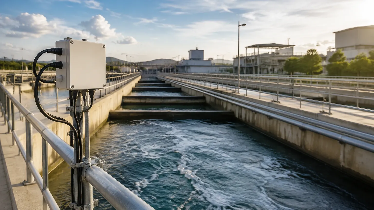
In municipal and industrial water treatment, ultrasonic flow meters are preferred for their ability to handle large pipe diameters without requiring a shutdown for installation.
* Leak Detection: High-accuracy transit-time meters are used in distribution networks to identify discrepancies between supply and consumption, helping utilities reduce non-revenue water (NRW).
* Influent and Effluent Monitoring: Doppler meters are frequently used to measure raw sewage or treated effluent that may contain residual solids or air bubbles.
* Pump Station Optimization: By monitoring the flow rates of large pumps, engineers can determine pump efficiency and schedule predictive maintenance.
2. Chemical and Petrochemical Processing
The non-contact nature of clamp-on ultrasonic meters is a significant advantage in chemical processing, where fluids are often corrosive, toxic, or under high pressure.
* Corrosive Fluid Measurement: Since the sensors do not touch the liquid, there is no risk of chemical attack on the instrument, and no risk of leakage through seals.
* Dosing and Batching: Precision transit-time meters ensure accurate chemical dosing in continuous processes.
* Refined Product Monitoring: In the oil and gas sector, ultrasonic meters are used for custody transfer of refined products, where high repeatability and low maintenance are critical.
3. HVAC and Energy Management
Ultrasonic flow meters are integral to Building Management Systems (BMS) for measuring thermal energy (BTU/kWh) in heating and cooling circuits.
* Chilled Water Systems: Monitoring the flow of chilled water allows for the calculation of cooling loads, enabling more efficient chiller plant operation.
* District Heating: Large-scale energy distribution networks use ultrasonic meters to bill customers accurately based on the volume of hot water delivered and the temperature differential.
4. Food and Beverage Industry
Hygiene is the primary concern in food production. Ultrasonic meters provide a solution that avoids the risk of contamination.
* Sanitary Measurement: Because clamp-on meters do not require pipe penetration, there are no "dead zones" where bacteria can grow. This makes them ideal for measuring milk, juices, and liquid sweeteners.
* CIP (Clean-In-Place) Monitoring: Ultrasonic meters can withstand the high temperatures and caustic chemicals used during cleaning cycles without degradation.
Selection Criteria: Choosing the Right Meter
Selecting the correct instrument for ultrasonic flow meter applications requires a detailed analysis of the process conditions. The following table provides a general guideline for technology selection:
| Feature | Transit-Time Ultrasonic | Doppler Ultrasonic |
| :— | :— | :— |
| Fluid Type | Clean liquids, gases, light oils | Slurries, aerated liquids, sewage |
| Suspended Solids | < 2% by volume | > 100 ppm (minimum particle size) |
| Accuracy | 0.5% to 1.0% of velocity | 2.0% to 5.0% of velocity |
| Pipe Material | Metal, plastic, glass | Metal, plastic |
| Installation | Clamp-on or Inline | Usually Clamp-on |
| Typical Use | Water, chemicals, fuels | Wastewater, mining tails, pulp |
Key Evaluation Factors
1. Pipe Material and Liner: Ultrasonic signals must pass through the pipe wall. While most metals (carbon steel, stainless steel) and plastics (PVC, PE) are excellent conductors, pipes with thick liners (like cement or bitumen) or those with significant internal corrosion can attenuate the signal.
2. Fluid Temperature: Extreme temperatures can affect the speed of sound in the medium and the integrity of the transducer couplant. High-temperature transducers are required for applications exceeding 120°C (248°F).
3. Flow Profile: For accurate measurement, the flow must be laminar and fully developed. This usually requires a straight run of pipe before and after the meter.
Installation Considerations and Best Practices
To ensure the success of ultrasonic flow meter applications, proper installation is as important as the technology itself. Even the most advanced meter will fail to provide accurate data if installed incorrectly.
Straight Run Requirements
Ultrasonic meters are sensitive to turbulence caused by elbows, valves, and pumps. A standard rule of thumb is to provide a straight pipe run of at least 10 diameters (10D) upstream and 5 diameters (5D) downstream of the sensor location. If the upstream flow is particularly disturbed (e.g., following a partially open valve), this may need to be increased to 20D or 30D.
Transducer Mounting Methods
For clamp-on meters, there are three common mounting configurations:
* V-Method: The signal bounces once off the opposite pipe wall. This is the standard for pipes ranging from 25 mm to 400 mm (1" to 16").
* Z-Method: Transducers are mounted on opposite sides of the pipe. This is used for large pipes or where the fluid is highly attenuative, as the signal only travels across the pipe once.
* W-Method: The signal bounces three times. This is used for very small pipes (typically under 50 mm or 2") to increase the transit time and improve resolution.
Coupling and Surface Preparation
For clamp-on sensors, the air gap between the transducer and the pipe must be eliminated. A coupling gel (ultrasonic grease) or a solid coupling pad is used to ensure the acoustic signal enters the pipe wall. The pipe surface should be cleaned of rust, loose paint, and debris to ensure a solid contact.
Limitations and Common Risks
While ultrasonic flow meters are highly versatile, they are not a "one-size-fits-all" solution. Engineers must be aware of potential limitations:
* Aeration and Bubbles: In transit-time applications, excessive air bubbles (usually >2%) will scatter the ultrasonic beam, leading to signal loss (often displayed as "Signal Strength Low" or "E6" errors on many controllers).
* Pipe Wall Condition: Heavy scaling or tuberculation inside an old pipe can absorb the signal or create unpredictable reflections, making measurement impossible.
* Laminar vs. Turbulent Flow: Most meters are calibrated for turbulent flow (Reynolds number > 4000). If the flow transitions into the laminar or transitional regime, the meter's accuracy may drift unless it features automatic Reynolds number correction.
Frequently Asked Questions (FAQ)
Q: Can ultrasonic flow meters measure steam?
A: Standard liquid ultrasonic meters cannot. However, specialized high-temperature transit-time meters designed for gas applications can measure dry or saturated steam, provided the velocity and pressure are within the sensor's operating range.
Q: How often do clamp-on ultrasonic meters need recalibration?
A: Because there are no moving parts and the sensors do not contact the fluid, the electronic components are very stable. Most manufacturers recommend a functional check every 1–2 years, but physical recalibration is rarely needed unless the pipe conditions change significantly.
Q: Do ultrasonic flow meters work on partially filled pipes?
A: Standard ultrasonic flow meters require a full pipe to function correctly. If the pipe is partially filled, the sound wave may not reach the receiving transducer. For partially filled pipes or open channels, specialized "area-velocity" flow meters that combine ultrasonic level sensing with Doppler velocity measurement are required.
Q: What is the minimum pipe size for ultrasonic measurement?
A: While technology exists for pipes as small as 10 mm (3/8"), most industrial clamp-on applications start at 15 mm to 25 mm (1/2" to 1"). Below this size, the transit time is so short that maintaining high accuracy becomes challenging.
Conclusion
Ultrasonic flow meter applications span the entirety of modern industry, from critical chemical dosing to massive municipal water distribution. By understanding the distinction between transit-time and Doppler methods, and by adhering to strict installation guidelines regarding straight runs and pipe preparation, engineers can achieve highly accurate, maintenance-free flow measurement.
As part of a broader industrial automation strategy, flow measurement often works in tandem with other instrumentation. For those looking to integrate these systems or explore further technical specifications, reviewing product options and application support on the Main Page is a recommended next step for any procurement or engineering project.