Ultrasonic Flow Meter Clamp on
Ultrasonic Flow Meter Clamp on
In modern industrial process control, the ability to measure fluid velocity without interrupting production or compromising the integrity of the piping system is a significant operational advantage. The ultrasonic flow meter clamp on technology provides a non-intrusive solution for measuring the volumetric flow of liquids. Unlike traditional electromagnetic or turbine meters, these devices are mounted to the exterior of the pipe, utilizing ultrasonic signals to determine flow rates. This guide explores the measurement principles, selection criteria, and installation requirements essential for engineering professionals.
Understanding the Principles of Ultrasonic Flow Measurement
Ultrasonic flow measurement relies on the propagation of high-frequency sound waves through a liquid medium. For clamp-on applications, two primary methods are utilized: Transit-Time and Doppler Effect. Understanding these principles is the first step in selecting the correct instrument for a specific application.
Transit-Time Method
Transit-time ultrasonic flow meters operate by transmitting and receiving ultrasonic pulses between two transducers. One transducer is placed upstream and the other downstream. The meter measures the time it takes for a sound pulse to travel from the upstream transducer to the downstream transducer ($t_{up}$) and compares it to the time taken for a pulse to travel from downstream to upstream ($t_{down}$).
When the fluid is moving, the pulse traveling with the flow moves faster than the pulse traveling against it. The time difference ($Δt$) is directly proportional to the flow velocity of the liquid. This method is highly accurate for clean liquids with low concentrations of suspended solids or entrained gases.
Doppler Effect Method
The Doppler method utilizes the frequency shift of an ultrasonic signal reflected off discontinuities in the flowing liquid, such as suspended particles or air bubbles. A transducer emits a signal of a known frequency; when this signal hits a moving particle, it is reflected back at a different frequency. The shift in frequency is proportional to the velocity of the particle, and by extension, the fluid. This technology is ideal for slurries, wastewater, and aerated liquids where transit-time signals would be attenuated or blocked.
Key Advantages of Clamp-on Technology
The primary appeal of an ultrasonic flow meter clamp on system is its non-invasive nature. Because the transducers do not come into contact with the process fluid, several engineering challenges are bypassed:
1. Zero Pressure Drop: Since there are no obstructions within the pipe, the system does not experience the energy loss associated with orifice plates or venturi meters.
2. Chemical Compatibility: The meter is isolated from corrosive or toxic fluids, eliminating the need for expensive exotic alloys in the meter body.
3. Ease of Retrofitting: Installation can occur while the plant is fully operational, avoiding costly shutdowns or pipe cutting.
4. Hygiene: In food, beverage, and pharmaceutical industries, the lack of internal sensors eliminates potential sites for bacterial growth or contamination.
For organizations looking to integrate these technologies into broader automation frameworks, reviewing the Main Page of specialized manufacturers like Welk can provide insights into how flow measurement integrates with level and pressure sensing systems.
Selection Criteria for Ultrasonic Flow Meter Clamp on Systems
Selecting the right ultrasonic flow meter requires a detailed analysis of the application environment. Engineers must confirm several parameters before procurement to ensure measurement reliability.
Pipe Material and Condition
The pipe must be able to conduct ultrasonic signals. Common materials such as carbon steel, stainless steel, ductile iron, and most plastics (PVC, PE, PVDF) are excellent conductors. However, pipes with internal linings—such as cement, glass, or bitumen—can pose challenges if the lining is not well-bonded to the pipe wall. Air gaps between the lining and the pipe will reflect the ultrasonic signal, preventing it from reaching the fluid.
Fluid Properties
* Cleanliness: Transit-time meters require relatively clean liquids (usually <2% particles or bubbles). Doppler meters require a minimum concentration of particles (typically >100 ppm) of a specific size (usually >75 microns).
* Temperature: Standard transducers typically handle up to 80°C or 120°C, but high-temperature versions are available for applications reaching 200°C or more.
* Viscosity: While ultrasonic meters are less sensitive to viscosity than some other types, extremely high viscosity can affect the flow profile, requiring Reynolds number compensation in the meter’s software.
Required Accuracy and Rangeability
Clamp-on meters typically offer an accuracy of ±1% to ±3% of the measured value after on-site calibration. They excel in wide turn-down ratios, often capable of measuring velocities from 0.01 m/s up to 12 m/s.
Installation and Commissioning Guidelines
The performance of an ultrasonic flow meter clamp on device is heavily dependent on the quality of the installation. Even the most advanced signal processor cannot compensate for poorly placed transducers.
Straight Pipe Run Requirements
To ensure a fully developed and stable flow profile, the transducers must be installed on a straight section of pipe. The industry standard recommendation is:
* Upstream: 10 times the nominal pipe diameter (10D).
* Downstream: 5 times the nominal pipe diameter (5D).
If the installation point is near a pump or a partially open valve, the upstream requirement may increase to 25D or 50D to allow turbulence to subside.
Transducer Mounting Methods
There are three common mounting configurations based on the pipe diameter and fluid properties:
1. V-Method: The signal crosses the pipe twice. This is the standard method for pipe diameters ranging from 25 mm to 400 mm. It provides a good balance between signal strength and path length.
2. Z-Method: The transducers are mounted on opposite sides of the pipe, and the signal crosses once. This is used for large pipes (above 400 mm) or where the fluid is highly attenuative.
3. W-Method: The signal crosses the pipe four times. This is used for very small pipes (typically below 50 mm) to increase the transit time difference and improve resolution.
Surface Preparation and Coupling
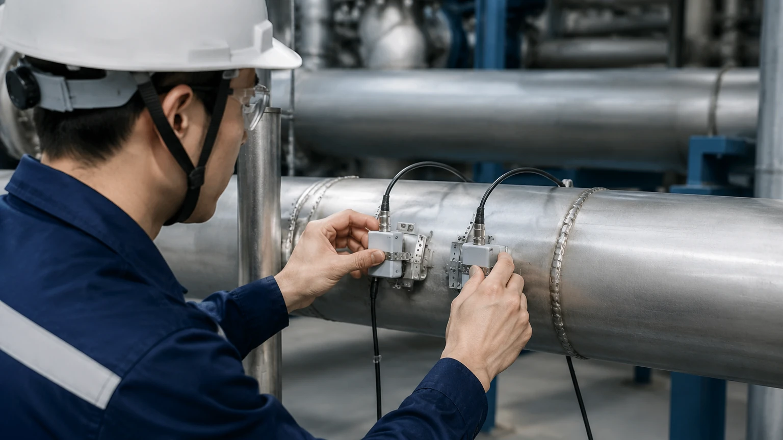
The pipe surface must be cleaned of rust, loose paint, and scale. A coupling agent (ultrasonic grease or gel) is applied between the transducer face and the pipe wall to eliminate air gaps. In permanent installations, solid epoxy or stainless-steel straps are used to maintain constant pressure on the transducers.
Technical Limitations and Operational Constraints
While versatile, clamp-on ultrasonic technology has specific limitations that must be addressed during the design phase:
* Aeration and Cavitation: Excessive bubbles in a transit-time system will scatter the signal, leading to a "signal loss" error. This is common in suction lines of pumps or in gravity-fed systems with high turbulence.
* Pipe Wall Thickness: Accurate measurement requires precise knowledge of the pipe wall thickness. If the wall thickness is unknown or varies due to internal corrosion, the calculated flow rate will be inaccurate. Ultrasonic thickness gauges should be used during installation to verify the pipe dimensions.
* Acoustic Short-Circuiting: In some very thick-walled pipes, the ultrasonic signal may travel through the pipe wall faster than through the fluid, creating noise that interferes with the measurement signal.
Comparison Table: Transit-Time vs. Doppler Technology
| Feature | Transit-Time | Doppler |
| :— | :— | :— |
| Primary Fluid Type | Clean liquids, water, oils | Slurries, wastewater, aerated fluids |
| Suspended Solids | < 2% by volume | > 100 ppm (application dependent) |
| Accuracy | Higher (typically ±1%) | Lower (typically ±2% to ±5%) |
| Pipe Size Range | 10 mm to 6000 mm | 25 mm to 6000 mm |
| Typical Applications | Potable water, cooling loops, chemicals | Raw sewage, mining tailings, paper pulp |
Maintenance and Long-term Reliability
Because there are no moving parts, the maintenance requirements for an ultrasonic flow meter clamp on are minimal. However, for permanent installations, the following checks should be performed annually:
1. Coupling Integrity: Ensure the coupling gel has not dried out or leaked. A drop in signal strength often indicates a need for re-greasing.
2. Transducer Alignment: Verify that the mounting straps have not loosened due to pipe vibration or thermal expansion.
3. Signal Diagnostics: Most modern transmitters provide diagnostic values such as signal quality (SQ), transit time ratio, and gain. Monitoring these values can predict potential failures before they occur.
Welk’s range of industrial measurement instruments, including radar and ultrasonic level sensors, often share similar digital communication protocols (HART, Modbus), allowing for a unified approach to maintenance and data acquisition across the facility. For detailed product specifications and application support, engineers are encouraged to visit the Main Page.
Frequently Asked Questions (FAQs)
Q: Can a clamp-on meter measure flow in a pipe that is only half full?
A: No. Ultrasonic flow meters require a full pipe to ensure the sound path is entirely submerged in the liquid. If the pipe is partially full, the signal will reflect off the air-liquid interface, resulting in an error.
Q: Does the pipe material affect the accuracy?
A: The pipe material affects the sound velocity. As long as the correct material and wall thickness are programmed into the transmitter, the accuracy remains high. Problems only arise with non-homogeneous materials like reinforced concrete or heavily corroded pipes.
Q: How do I handle pipes with heavy scaling?
A: Internal scaling acts as an additional layer with unknown acoustic properties. It can attenuate the signal and change the internal diameter (ID). In such cases, it is best to install the meter on a newer section of the pipe or use a Doppler meter if the scaling creates enough turbulence.
Q: Is it necessary to calibrate the meter on-site?
A: While factory calibration is standard, on-site calibration against a known reference (like a tank draw-down test) is recommended for high-precision applications to account for specific pipe wall conditions and flow profiles.
By following these technical guidelines and understanding the underlying physics of ultrasonic propagation, engineers can successfully implement clamp-on flow measurement solutions that provide reliable data without the risks and costs associated with traditional inline flow meters.