Vortex Modelling
Vortex Modelling
In industrial fluid processing, the transition from static storage to dynamic discharge often introduces complex hydraulic phenomena. Among the most challenging for instrumentation engineers is the formation of a vortex. Vortex modelling serves as a critical predictive tool used to understand fluid behavior during drainage or agitation, ensuring that level measurement instruments provide reliable data even under turbulent conditions. For facilities managing high-flow rates or viscous chemicals, integrating vortex modelling into the initial design phase is essential for preventing pump cavitation and measurement signal loss.
Understanding Vortex Formation in Industrial Vessels
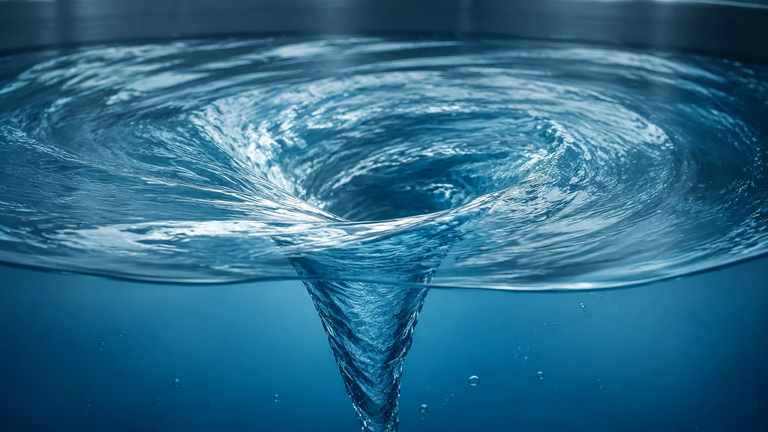
A vortex is essentially a mass of fluid rotating around a central axis. In industrial tanks, this typically manifests as a surface depression that can extend downward toward the outlet. There are two primary types of vortices encountered in process engineering: the free vortex and the forced vortex.
Free Vortex
This occurs naturally during drainage due to the conservation of angular momentum. As fluid moves toward the outlet, its tangential velocity increases. If the liquid level drops below a certain threshold, known as the critical submergence depth, the vortex can reach the outlet, drawing air or gas into the piping system.
Forced Vortex
This is typically generated by mechanical energy, such as an agitator or mixer. While necessary for blending, forced vortices create a highly non-linear fluid surface that can fluctuate rapidly, presenting a significant challenge for non-contact level sensors.
Measurement principles for most industrial sensors rely on a relatively flat, perpendicular surface to reflect signals. When a vortex forms, the surface becomes parabolic or conical. This geometry scatters the emitted energy from radar or ultrasonic pulses, leading to "signal hunting" or complete loss of echo. Understanding these principles via vortex modelling allows engineers to select the appropriate hardware from the Main Page to maintain process control.
The Impact of Vortexing on Level Measurement Accuracy
Vortexing does not merely affect the fluid flow; it fundamentally alters the environment in which level sensors operate. Different technologies respond to these changes in varying ways:
1. Radar Level Meters: High-frequency radar (such as 80 GHz units) offers a narrow beam angle, which can sometimes "see" past the sloping sides of a vortex to the bottom. However, if the vortex is centered directly under the sensor, the signal may be reflected away from the receiver, resulting in an error.
2. Ultrasonic Sensors: These are highly sensitive to surface turbulence. The air-foam interface often associated with high-velocity vortices can absorb ultrasonic energy, leading to inaccurate readings.
3. Hydrostatic Transmitters: While less affected by surface geometry, hydrostatic sensors can be influenced by the pressure changes caused by the centrifugal force of a rotating fluid mass. This can result in a "false high" or "false low" reading depending on the sensor's radial position relative to the vortex core.
Methodologies for Vortex Modelling
To mitigate these risks, engineers employ vortex modelling through three primary methodologies: empirical calculations, physical scale modelling, and Computational Fluid Dynamics (CFD).
Empirical Calculations and Critical Submergence
The simplest form of modelling involves calculating the critical submergence ($S_c$). A common engineering rule of thumb for preventing air entrainment is:
$$S_c = d (1 + 0.5 Fr)$$
Where:
* $S_c$: Critical submergence (meters)
* $d$: Diameter of the outlet pipe (meters)
* $Fr$: Froude Number (dimensionless)
Computational Fluid Dynamics (CFD)
Modern vortex modelling relies heavily on CFD software. By creating a digital twin of the tank, engineers can simulate various flow rates and fluid viscosities. CFD allows for the visualization of velocity vectors and pressure gradients, identifying exactly where a vortex will form and how deep it will penetrate. This data is invaluable for determining the optimal mounting position for radar or ultrasonic level transmitters.
Physical Scale Modelling
For large-scale infrastructure projects, such as water treatment intake stations or massive chemical reactors, physical models are built using Froude scaling laws. This ensures that the ratio of inertial forces to gravitational forces remains constant between the model and the full-scale installation, allowing for the observation of vortex behavior in a controlled environment.
Engineering Mitigation and Sensor Selection
Once vortex modelling identifies a potential issue, several engineering steps can be taken. The following table provides a selection guide for level measurement technologies in vessels where vortexing is predicted.
| Technology | Suitability in Vortexing | Mitigation Requirement |
| :— | :— | :— |
| 80GHz Radar | High | Use of tracking algorithms and narrow beam angles. |
| Guided Wave Radar (GWR) | Very High | Probe must be anchored to prevent bending from fluid forces. |
| Ultrasonic | Moderate | Requires stilling wells or bypass pipes. |
| Hydrostatic | High | Position sensor away from high-velocity zones. |
| Magnetic Level Gauge | Excellent | Naturally immune to internal tank turbulence. |
| Level Switches | High | Use of time-delay functions to prevent chattering. |
Anti-Vortex Plates and Baffles
One of the most effective ways to neutralize a vortex is the installation of anti-vortex plates over the outlet. These plates break the rotational flow, allowing the liquid level to drop much lower before air entrainment occurs. Similarly, internal baffles can be added to the tank walls to disrupt the circular motion caused by agitators.
Installation Guidelines for Turbulent Environments
When installing level measurement instruments in tanks prone to vortexing, follow these technical considerations:
* Offset Mounting: Never mount a non-contact sensor (Radar/Ultrasonic) directly over the center of the tank or the outlet pipe, as this is where the vortex core is most likely to form. Position the sensor at 1/2 to 2/3 of the tank radius.
* Stilling Wells: For ultrasonic and standard radar sensors, a stilling well (a vertical pipe with vent holes) provides a calm liquid surface for measurement, effectively isolating the sensor from the vortex.
* Damping Settings: Increase the damping or integration time in the sensor’s software. This helps the transmitter average out the fluctuations caused by the turbulent surface, providing a more stable output signal.
* Beam Angle Awareness: Ensure the sensor’s beam does not intersect with internal baffles or the sloping sides of the vortex cone. A narrower beam (e.g., 3 degrees) is always preferable in these applications.
Limitations of Vortex Modelling
While vortex modelling is a powerful tool, it has factual boundaries that engineers must respect:
* Fluid Variability: Modelling is often based on specific viscosity and density. If the process fluid changes (e.g., temperature fluctuations affecting viscosity), the vortex behavior may deviate from the model.
* Scale Effects: In physical modelling, surface tension effects (Weber Number) can become disproportionately large in very small models, leading to inaccuracies in predicting air entrainment.
* Computational Intensity: High-fidelity CFD models require significant processing power and expert interpretation. Simplified models may fail to capture transient, non-steady-state vortices that appear only during specific phases of a process.
Frequently Asked Questions
Q: Can a vortex be completely eliminated in a stirred tank?
No, a forced vortex is a natural byproduct of agitation. However, its depth can be minimized using baffles, and its impact on measurement can be mitigated by using guided wave radar or stilling wells.
Q: At what depth does a vortex usually start to affect radar sensors?
It depends on the outlet velocity, but typically when the liquid level is less than two times the outlet pipe diameter, the surface begins to deform significantly enough to scatter radar signals.
Q: Is vortex modelling necessary for small tanks?
For tanks under 500 liters, empirical rules of thumb and proper sensor placement are usually sufficient. Modelling is generally reserved for large-scale processes or highly critical applications where pump failure is not an option.
Q: How does fluid viscosity affect vortex modelling?
Higher viscosity fluids tend to resist vortex formation but, once formed, the vortex is more stable and takes longer to dissipate. Modelling must account for the Reynolds number of the specific fluid.
By combining rigorous vortex modelling with the advanced instrumentation found on our Main Page, process engineers can ensure continuous, accurate level monitoring. Whether through the use of anti-vortex hardware or the selection of high-frequency radar sensors, addressing fluid dynamics at the design stage is the most cost-effective path to operational reliability.