Water Tank Monitoring System
Water Tank Monitoring System
In industrial and municipal environments, the management of water resources requires more than simple visual inspections. A robust water tank monitoring system is essential for ensuring operational continuity, preventing overflows, and protecting infrastructure from dry-run conditions. These systems integrate advanced sensing technologies with data transmission modules to provide real-time visibility into storage levels, whether the medium is potable water, industrial process water, or wastewater.
Modern monitoring solutions have evolved from basic mechanical floats to sophisticated digital arrays. Choosing the correct technology requires an understanding of the physical principles governing level measurement, the environmental constraints of the installation site, and the specific requirements of the application. As a professional manufacturer, Welk provides a range of instruments designed to integrate seamlessly into a comprehensive water tank monitoring system, ensuring accuracy and long-term reliability.
Measurement Principles in Water Tank Monitoring
Before selecting components for a monitoring system, it is critical to understand how different sensors interact with the liquid and the tank environment. Each technology has distinct physical foundations that dictate its suitability for specific scenarios.
Ultrasonic Level Measurement (Non-Contact)
Ultrasonic sensors operate on the Time-of-Flight (ToF) principle. The sensor head contains a piezoelectric crystal that emits high-frequency sound pulses. These waves travel through the air, strike the water surface, and reflect back to the sensor. By measuring the time elapsed between emission and reception, and knowing the speed of sound in air, the system calculates the distance to the liquid surface.
* Advantages: Non-contact nature prevents contamination and corrosion; no moving parts reduce maintenance.
* Limitations: Performance can be degraded by heavy foam, steam, or significant temperature fluctuations that alter the speed of sound. They also have a "dead zone" (blocking distance) directly beneath the sensor where measurement is impossible.
Radar Level Measurement (Non-Contact)
Radar sensors also use the ToF principle but employ electromagnetic microwave pulses instead of sound waves. High-frequency radar (such as 80GHz) is increasingly preferred in a water tank monitoring system due to its narrow beam angle and high precision. Unlike sound, microwaves are largely unaffected by air temperature, pressure, or vacuum conditions.
* Advantages: Extreme accuracy (often within ±2mm); capable of penetrating steam and dust; works well in narrow tanks or tanks with internal obstructions.
* Limitations: Higher initial investment compared to ultrasonic or hydrostatic methods.
Hydrostatic Level Measurement (Contact)
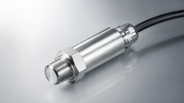
Hydrostatic transmitters measure the pressure exerted by the liquid column above the sensor. Based on the formula $P = \rho gh$ (where P is pressure, $\rho$ is liquid density, $g$ is gravity, and $h$ is height), the sensor converts the measured pressure into a level reading. These are typically submersible transducers or side-mounted pressure transmitters.
* Advantages: Simple installation; highly reliable for deep tanks or reservoirs; unaffected by surface foam or turbulence.
* Limitations: Requires contact with the liquid; density changes (e.g., due to significant temperature shifts) can affect accuracy unless compensated.
Magnetic Level Gauges and Switches
Magnetic systems utilize a float containing an internal magnet that moves with the water level. This float interacts with an external indicator or a series of reed switches. While often used for visual local indication, they can be equipped with reed-chain transmitters to provide a 4-20mA signal to a remote monitoring system.
* Advantages: Provides a clear visual backup; requires no power for the local display; highly durable.
* Limitations: Mechanical parts are subject to wear or fouling if the water contains high levels of debris or scaling minerals.
Components of a Complete Water Tank Monitoring System
A functional system is comprised of more than just a sensor. To provide actionable data, the following components must work in unison:
1. Sensing Element: The primary instrument (Radar, Ultrasonic, or Hydrostatic) that detects the water level.
2. Signal Transmitter: Converts the raw sensor data into a standardized industrial signal, such as 4-20mA, RS485 (Modbus), or HART.
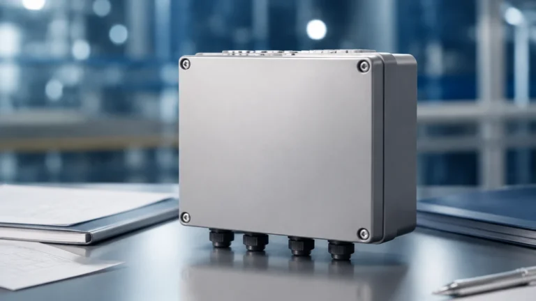
3. Local Controller/Display: Often mounted at eye level near the tank, this unit provides immediate readings and may include relays for pump control or high/low alarms.
4. Data Logger/Gateway: In remote or large-scale applications, a gateway transmits data via cellular (NB-IoT/4G), LoRaWAN, or Ethernet to a central server.
5. Software Interface: A cloud-based dashboard or SCADA system where users can view historical trends, configure alerts, and manage multiple tanks simultaneously.
For engineers looking to source individual components or integrated solutions, the Main Page of our product catalog offers detailed specifications for each sensor type.
Practical Selection Table
Choosing the right technology depends on the specific parameters of your water storage project. Use the following table as a general guide for initial selection:
| Technology | Typical Accuracy | Max Range | Media Suitability | Relative Cost | Best Application |
| :— | :— | :— | :— | :— | :— |
| Ultrasonic | ±0.25% to 0.5% | 15m – 20m | Clean water, no foam | Moderate | Standard municipal water tanks |
| 80GHz Radar | ±2mm | 120m | All liquids, steam, foam | High | Process water, chemical tanks, narrow silos |
| Hydrostatic | ±0.1% to 0.5% | 200m+ | Clean or grey water | Low to Moderate | Deep wells, reservoirs, underground tanks |
| Magnetic Gauge | ±5mm to 10mm | 6m (standard) | Clean liquids | Moderate | Boiler feed water, high-pressure vessels |
Installation Considerations
The reliability of a water tank monitoring system is heavily dependent on proper installation. Even the most expensive radar sensor will fail to provide accurate data if positioned incorrectly.
1. Avoiding Obstructions
For non-contact sensors (Radar and Ultrasonic), the signal beam must have a clear path to the water surface. Avoid installing sensors near internal ladders, heating coils, or support struts. If using radar, ensure the beam angle does not intersect with the tank wall, which can cause false echoes.
2. Positioning Relative to Inlets
Never install a level sensor directly above or adjacent to an inlet pipe. The turbulence and splashing created by incoming water will cause erratic readings and may physically damage submersible hydrostatic sensors. Ideally, the sensor should be placed in a "quiet" zone of the tank.
3. Standoff Pipes and Nozzles
When installing sensors on tank nozzles, ensure the nozzle height does not exceed the sensor's requirements. For ultrasonic sensors, the nozzle must be short enough that the "dead zone" remains within the pipe or above the maximum fill level. For radar, the nozzle should be smooth to prevent signal interference.
4. Atmospheric Venting
Hydrostatic submersible sensors must have a vented cable. This vent tube allows the sensor to compensate for changes in atmospheric pressure. If this tube is blocked or kinked, the level reading will drift as weather patterns change.

Limitations and Common Risks
While modern systems are highly advanced, engineers must be aware of potential failure points:
* Environmental Interference: In outdoor tanks, extreme heat can cause the air space above the water to stratify in temperature, affecting ultrasonic accuracy. In such cases, radar is the superior choice.
* Build-up and Scaling: In hard water applications, calcium deposits can build up on the face of ultrasonic transducers or the diaphragms of hydrostatic sensors. Regular inspection schedules are necessary for these environments.
* Power Supply Stability: Industrial sensors are sensitive to voltage spikes. A stable power supply and proper grounding are essential, especially in areas prone to lightning or heavy electrical machinery usage.
* Signal Loss: In wireless water tank monitoring systems, the signal can be blocked by metal structures or heavy vegetation. Site surveys should be conducted to ensure reliable connectivity.
Frequently Asked Questions (FAQ)
Q: Can one system monitor multiple tanks?
A: Yes. Most multi-channel controllers or PLC-based systems can aggregate data from several sensors. In cloud-based IoT systems, a single gateway can often support dozens of sensors via Modbus or wireless protocols.
Q: How often do these sensors need calibration?
A: Hydrostatic and ultrasonic sensors typically require annual calibration checks. Radar sensors are extremely stable and may operate for several years without significant drift, though regulatory requirements in some industries may dictate more frequent verification.
Q: Is it possible to monitor water tanks in remote areas without mains power?
A: Absolutely. Low-power hydrostatic or ultrasonic sensors can be paired with solar-powered RTUs (Remote Terminal Units) and cellular telemetry to provide monitoring in off-grid locations.
Q: What is the difference between a level switch and a level transmitter?
A: A level switch provides a point-level alert (e.g., "tank is full" or "tank is empty"). A level transmitter provides continuous measurement (e.g., "tank is at 64%"). A comprehensive monitoring system usually utilizes a transmitter for data and switches for redundant high-level safety shut-offs.
Conclusion
Implementing an effective water tank monitoring system is a critical step in industrial process optimization and resource management. By selecting the appropriate measurement principle—whether it be the precision of 80GHz radar, the cost-effectiveness of hydrostatic pressure, or the versatility of ultrasonic waves—operators can ensure accurate data collection and long-term system durability.
Proper attention to installation details, such as avoiding turbulence and ensuring clear signal paths, will mitigate the most common causes of system failure. As water scarcity and operational costs continue to rise, the transition from manual monitoring to automated, high-precision systems is no longer an option but a necessity for modern industrial infrastructure.