Pressure Transducer Differential
Pressure Transducer Differential
In the field of industrial process control, the pressure transducer differential (often referred to as a DP transmitter or sensor) serves as a cornerstone for measuring not only pressure drops but also fluid level, flow rate, and density. Unlike a standard gauge pressure sensor that measures pressure relative to the atmosphere, a differential pressure instrument measures the difference between two distinct points in a system. For engineers and plant operators, understanding the nuances of this technology is essential for ensuring accuracy in complex environments such as pressurized chemical reactors, water treatment facilities, and oil and gas pipelines.
As a professional manufacturer, Welk provides a range of level measurement instruments that leverage these principles to deliver high-precision data. This guide explores the mechanical principles, application strategies, and selection criteria for differential pressure technology in modern industrial automation.
Understanding the Measurement Principle
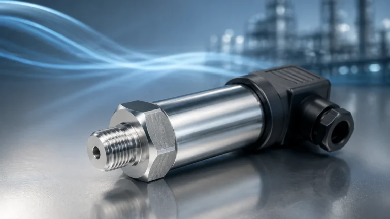
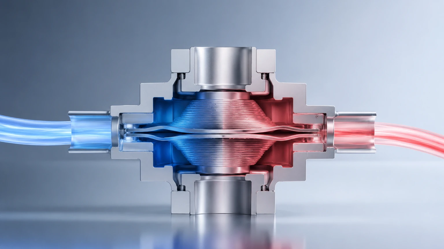
A pressure transducer differential operates by sensing two separate pressures simultaneously. The device typically features two process connections, labeled as the "High Pressure" (H) side and the "Low Pressure" (L) side. The internal sensing element—usually a metallic or ceramic diaphragm—is positioned between these two ports.
The Mechanical Interface
When pressure is applied to both sides of the diaphragm, the component does not respond to the absolute magnitude of the pressure (static pressure) but rather to the resultant force caused by the inequality between the two sides. If the pressure on the High side is 5.0 bar and the pressure on the Low side is 4.8 bar, the transducer detects a differential of 0.2 bar (20 kPa).
Transduction Technologies
Modern industrial transducers utilize several methods to convert this mechanical displacement into an electrical signal:
1. Piezoresistive Strain Gauges: Small resistors are etched onto a silicon or metal diaphragm. As the diaphragm flexes due to differential pressure, the resistance changes, which is measured via a Wheatstone bridge circuit.
2. Capacitive Sensing: The sensing diaphragm acts as a moving electrode between two fixed plates. A change in pressure alters the capacitance, which is then converted into a high-resolution digital or analog signal (typically 4-20mA or HART).
3. Resonant Wire/Crystal: These sensors measure the change in vibration frequency of a wire or crystal under tension, offering exceptional stability and long-term accuracy.
Role in Industrial Level Measurement
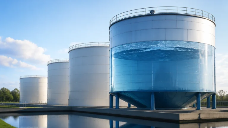
While radar and ultrasonic sensors are popular for non-contact level measurement, the pressure transducer differential remains the gold standard for pressurized vessels. In an open-to-atmosphere tank, a simple hydrostatic transmitter at the bottom is sufficient because the "low side" is effectively the ambient air. However, in a closed system, the vapor space above the liquid exerts its own pressure, which would give a false level reading if not accounted for.
The Closed Tank Calculation
To find the true liquid level in a pressurized tank, the transducer subtracts the head pressure of the gas/vapor from the total pressure measured at the bottom of the tank. The formula used is:
ΔP = (ρ × g × h) + P_vapor – P_vapor
Which simplifies to:
ΔP = ρ × g × h
Where:
* ΔP is the differential pressure measured.
* ρ (Rho) is the density of the liquid (kg/m³).
* g is the gravitational constant (9.81 m/s²).
* h is the height of the liquid (m).
By isolating the hydrostatic head of the liquid, the pressure transducer differential provides a linear representation of the level regardless of fluctuations in the tank's internal blanket pressure.
Key Selection Criteria for DP Transducers
Choosing the right instrument requires more than just knowing the expected pressure range. Engineers must evaluate the static pressure, chemical compatibility, and environmental conditions of the installation site. For a comprehensive overview of available technologies, engineers can Review product options and application support to align instrument specifications with specific project needs.
Selection Comparison Table
| Feature | Standard DP Transducer | Remote Diaphragm Seal DP | Multivariable DP |
| :— | :— | :— | :— |
| Primary Use | Clean liquids, gases, steam | Corrosive, viscous, or hot fluids | Combined flow, level, and temp |
| Accuracy | High (0.04% to 0.075% span) | Moderate (affected by capillaries) | High (compensated) |
| Process Temp | Up to 120°C (direct mount) | Up to 400°C+ with capillaries | Up to 150°C |
| Maintenance | Low (requires impulse lines) | Low (no impulse lines to clog) | Moderate (complex electronics) |
| Cost | Baseline | Higher (due to seals/fill fluid) | Premium |
Static Pressure Rating
It is vital to distinguish between the differential range (e.g., 0-500 mbar) and the maximum working pressure (e.g., 160 bar). A sensor must be able to withstand the full system pressure on both sides without mechanical failure or significant "zero shift" errors.
Installation Best Practices and Configurations
The accuracy of a pressure transducer differential is often determined more by its installation than by its factory calibration. Proper piping and mounting are essential to prevent measurement lag or false readings.
Impulse Piping and Manifolds
Impulse lines are the small-bore pipes that carry the process pressure to the transducer.
* Slope: Lines should be sloped at least 1:12 (approx. 8%) to allow gas bubbles to rise back into the tank (for liquid service) or condensate to drain back (for gas service).
* Manifolds: A 3-valve or 5-valve manifold is standard. These allow the operator to isolate the instrument, equalize the pressure for zero-checking, and bleed the lines without shutting down the process.
Wet Leg vs. Dry Leg
In level applications where the vapor above the liquid might condense, a "Wet Leg" configuration is used. The low-pressure impulse line is intentionally filled with a reference fluid (often the process liquid or a stable oil) to prevent erratic readings caused by random condensation. If the vapor does not condense at ambient temperatures, a "Dry Leg" is used, where the low-pressure line remains filled with gas.
Remote Seals and Capillaries
For applications involving hygienic requirements (food and beverage) or highly corrosive chemicals, remote diaphragm seals are used. The pressure is transmitted from a remote sensing face to the transducer via a capillary tube filled with silicone oil or another transmission fluid. While this protects the instrument, engineers must account for the thermal expansion of the fill fluid, which can introduce small errors in outdoor installations with high diurnal temperature swings.
Limitations and Operational Risks
While versatile, the pressure transducer differential is not a "fit and forget" solution for every scenario. Awareness of its limitations ensures better system design.
1. Density Sensitivity: Since the measurement relies on hydrostatic head, any change in the liquid's density (due to temperature changes or concentration shifts) will directly affect the level reading. If the density is not constant, a multivariable transmitter or temperature compensation algorithm is required.
2. Impulse Line Clogging: In wastewater or slurry applications, the small-diameter impulse lines are prone to plugging. In these cases, a flush-membrane level transmitter or a non-contact ultrasonic sensor may be more appropriate.
3. Zero Shift: High static pressures can cause a slight physical deformation in the sensor body, leading to a "zero shift." High-quality transducers from manufacturers like Welk are characterized at the factory to minimize this effect, but it should always be verified during commissioning.
4. Ambient Temperature Effects: The electronics and the mechanical sensing elements are sensitive to extreme cold or heat. Heat tracing or insulated enclosures may be necessary for outdoor installations in frigid climates to prevent the process fluid in the impulse lines from freezing.
Frequently Asked Questions
How often should a DP transducer be calibrated?
In most stable industrial environments, an annual calibration check is standard. However, in critical safety loops or high-vibration areas, a six-month interval may be required. Many modern units feature "smart" diagnostics that can alert operators to drift or sensor failure before it impacts the process.
Can I use a differential pressure sensor for flow measurement?
Yes. By placing an orifice plate, Venturi tube, or Pitot tube in a pipe, the pressure transducer differential measures the pressure drop across the restriction. According to Bernoulli's principle, the square root of this differential pressure is proportional to the flow rate.
What is the advantage of a 5-valve manifold over a 3-valve manifold?
A 5-valve manifold includes two additional vent/drain valves. This allows for safer venting of process fluids to a closed recovery system rather than the atmosphere, which is critical when handling hazardous or expensive chemicals.
How does mounting position affect the zero point?
The weight of the internal fill fluid and the diaphragm itself can cause a small zero offset if the transmitter is tilted. Always mount the instrument in the orientation specified by the manufacturer and perform a "zero trim" after installation to cancel out mounting-position effects.
Summary of Application Engineering
The pressure transducer differential remains a primary tool for engineers due to its reliability and well-understood physics. Whether monitoring the pressure drop across a filter to schedule maintenance or managing the inventory of a pressurized LNG tank, the accuracy of the data depends on matching the sensor material to the process fluid and ensuring the installation prevents the entrapment of air or condensate.
For projects requiring customized OEM/ODM services or specialized materials like Tantalum or Hastelloy for corrosive environments, selecting a manufacturer with a robust quality control framework is paramount. By adhering to the principles of hydrostatic measurement and following rigorous installation standards, facilities can achieve long-term stability and safety in their level and pressure monitoring loops. For further technical specifications and to explore the full range of industrial measurement solutions, visit the Main Page of the primary technical reference site.