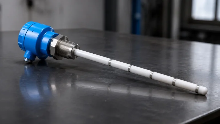
Well Level Transducer
Well Level Transducer
In industrial water management, agricultural irrigation, and municipal supply systems, monitoring the depth of water in wells and boreholes is a critical operational requirement. A well level transducer is the primary instrument used to provide continuous, real-time data on water levels, ensuring that pumps operate within safe parameters and that aquifers are managed sustainably. This guide explores the engineering principles, selection criteria, and installation best practices for these essential devices.
Understanding the Hydrostatic Measurement Principle
Before selecting a specific well level transducer, it is essential to understand the physical principle that governs its operation. Most industrial well sensors utilize the hydrostatic pressure method. This principle states that the pressure at a specific depth within a static liquid is directly proportional to the height of the liquid column above that point.
Mathematically, this is expressed as:
P = ρ × g × h
Where:
* P is the hydrostatic pressure.
* ρ (rho) is the density of the liquid (e.g., water).
* g is the gravitational acceleration.
* h is the height of the liquid column.
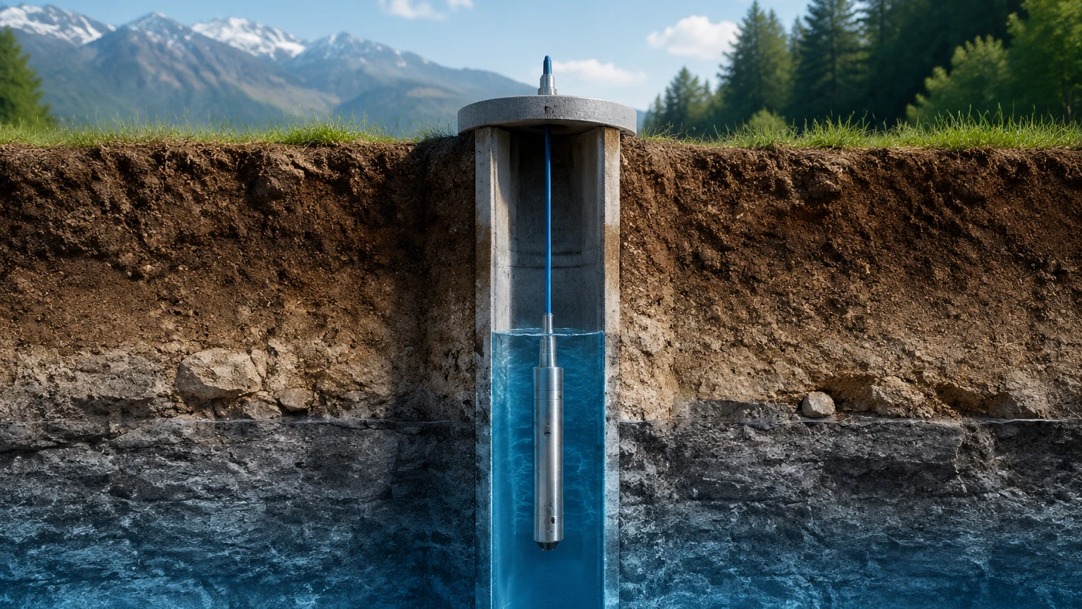
A submersible well level transducer is lowered into the water to a fixed depth. The sensor diaphragm detects the pressure exerted by the water column. Because the density of water and gravity are relatively constant, the transducer can accurately calculate the height of the water above the sensor. To ensure accuracy, the sensor must also account for atmospheric pressure acting on the surface of the water. This is achieved through a specialized vent tube integrated into the sensor cable, which allows the internal side of the pressure sensing element to remain at the same pressure as the atmosphere, effectively "canceling out" barometric fluctuations.
Core Components of a Well Level Transducer
A professional-grade well level transducer is engineered to withstand long-term submersion in potentially harsh environments. The assembly typically consists of three primary elements:
1. The Sensor Head: This housing contains the sensing element (usually a piezoresistive silicon or ceramic strain gauge) and the signal conditioning electronics. In high-quality units, the housing is constructed from 304 or 316L stainless steel, or even titanium for brackish or corrosive water applications.
2. The Submersible Cable: This is more than just a power and signal conduit. It contains a high-strength tension member (often Kevlar) to prevent stretching under the weight of long cable runs, and a hollow vent tube for atmospheric compensation. The outer jacket is typically made of Polyurethane (PUR) or Polyethylene (PE) for water resistance and durability.
3. The Signal Output: The internal electronics convert the raw pressure reading into a standardized industrial signal. The most common output is 4-20mA, which is highly resistant to electrical noise over long distances. Digital options like RS485 (Modbus RTU) are increasingly popular for integration into SCADA systems and remote telemetry units.
Selection Criteria for Industrial Well Monitoring
Choosing the right well level transducer requires a detailed assessment of the well's physical characteristics and the required data precision. Engineers should evaluate the following factors:
Measurement Range and Depth
The range of the transducer should be selected based on the maximum expected water column height, not the total depth of the well. For example, if a well is 100 meters (328 ft) deep, but the water level never rises more than 40 meters (131 ft) above the pump, a 50-meter (164 ft) range sensor provides better resolution than a 100-meter sensor.
Accuracy Requirements
Standard industrial transducers typically offer an accuracy of 0.5% of the Full Scale (FS). For scientific groundwater research or critical custody transfer applications, high-precision models with 0.1% or 0.25% FS accuracy are available. It is important to note that accuracy often includes the effects of linearity, hysteresis, and repeatability.
Material Compatibility
While clean groundwater is generally non-corrosive, some deep wells may contain high levels of salinity, hydrogen sulfide, or other minerals. In such cases, a standard stainless steel housing may suffer from pitting. Titanium housings and Tefzel cables are recommended for high-salinity or chemically aggressive environments.
Practical Selection Table
The following table provides a general reference for selecting a well level transducer based on common application profiles.
| Application Type | Recommended Housing | Cable Material | Typical Output | Range (m) |
| :— | :— | :— | :— | :— |
| Shallow Domestic Well | 304 Stainless Steel | PE (Polyethylene) | 4-20mA | 0-20m |
| Deep Municipal Borehole | 316L Stainless Steel | PUR (Polyurethane) | 4-20mA / RS485 | 0-200m |
| Coastal/Brackish Water | Titanium | Tefzel / PUR | RS485 (Modbus) | 0-100m |
| Chemical/Industrial Sump | 316L or Ceramic | PTFE / FEP | 0-10V / 4-20mA | 0-50m |
For project managers and engineers looking to specify equipment for complex systems, reviewing the Main Page of a dedicated manufacturer like Welk can provide a broader overview of available technologies and customization options.
Installation and Commissioning Guidelines
Correct installation is the most significant factor in the longevity and reliability of a well level transducer. Even the highest quality sensor will fail or provide inaccurate data if installed improperly.
1. Cable Support and Strain Relief
The weight of a long submersible cable can be substantial. It should never be supported solely by the electrical connections at the wellhead. Use a dedicated cable clamp or Kellems grip to secure the cable at the top of the well. This prevents the internal wires and the vent tube from being crushed or stretched.
2. Positioning Relative to the Pump
To avoid turbulence and the "drawdown" effect caused by pump activation, the transducer should be installed at least a few meters away from the pump intake if possible. If the well diameter is narrow, the sensor may need to be installed in a "still well" or a perforated PVC pipe to shield it from rapid water movement and physical vibration.
3. Vent Tube Protection
The vent tube must remain clear of obstructions. If moisture enters the vent tube, it can condense and block the air path, or worse, migrate down to the electronics. Always use a desiccant cartridge (vent filter) at the end of the cable termination. This cartridge should be inspected regularly and replaced when the desiccant changes color (usually from blue to pink).
4. Lightning and Surge Protection
Because wells are often located in open areas and the cable acts as a long antenna, well level transducers are highly susceptible to lightning strikes. Installing a surge protector at the wellhead and ensuring proper grounding of the sensor shield is a mandatory step for industrial installations.
Limitations, Risks, and Environmental Factors
While hydrostatic well level transducers are highly reliable, they are not without limitations. Engineers should be aware of the following risks:
* Silt and Sediment Accumulation: In wells with high sediment content, silt can accumulate around the sensor diaphragm. This can cause a "drift" in readings or eventually block the sensor entirely. Regular cleaning or the use of a protective cage is recommended.
* Specific Gravity Variations: The transducer assumes a constant liquid density. If the water temperature changes significantly or if the salinity fluctuates, the density (ρ) changes, which will introduce a small error in the level calculation. Some advanced transducers include an integrated temperature sensor to compensate for these effects.
* Atmospheric Blockage: As mentioned previously, if the vent tube is kinked or blocked by moisture, the sensor cannot compensate for barometric pressure changes. A 10 mbar change in atmospheric pressure can result in an error of approximately 10 cm (4 inches) in the water level reading.
Frequently Asked Questions (FAQs)
Q: How deep can a well level transducer be submerged?
A: Standard industrial models are rated for depths up to 200 meters (approx. 650 ft), but specialized deep-well versions can operate at depths exceeding 500 meters (1,640 ft). The limitation is usually the structural integrity of the cable and the pressure rating of the sensor housing.
Q: Can I use a well level transducer in a tank?
A: Yes, the hydrostatic principle works identically in tanks. However, for pressurized tanks, a differential pressure transmitter is required instead of a vented submersible transducer, as the headspace pressure must be subtracted from the total pressure.
Q: How often should I calibrate my well level transducer?
A: For most industrial applications, an annual calibration check is sufficient. In high-accuracy scientific monitoring, semi-annual checks may be required. Most drift occurs due to sediment buildup or desiccant exhaustion rather than electronic failure.
Q: What is the difference between a pressure transducer and a level transmitter?
A: In the context of well monitoring, the terms are often used interchangeably. Technically, the "transducer" is the sensing element that converts pressure to a low-level signal, while the "transmitter" includes the electronics that convert that signal into a standard industrial output like 4-20mA.
Conclusion
The well level transducer is a foundational tool for modern water management. By understanding the hydrostatic principle and carefully selecting materials and ranges based on the specific borehole environment, operators can ensure years of maintenance-free service. Proper installation—focusing on cable support, vent tube integrity, and surge protection—remains the most effective way to protect the investment and maintain data accuracy. For those exploring the integration of these sensors into broader automation frameworks, consulting professional resources and manufacturer specifications is highly recommended to ensure the selected solution meets all technical and regulatory requirements.