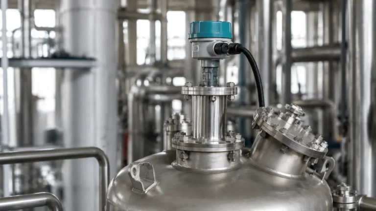
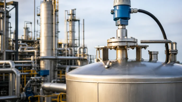
5400 Radar Level Transmitter
5400 Radar Level Transmitter: A Practical Engineering Guide to Implementation and Selection
In the landscape of industrial automation, precise level measurement is a cornerstone of process safety, inventory management, and operational efficiency. Among the various technologies available, non-contacting radar has emerged as a premier solution for challenging environments. The 5400 radar level transmitter represents a significant category of high-performance instrumentation designed to provide reliable data in the presence of vapors, dust, and varying temperatures.
This guide explores the underlying physics, selection criteria, and installation requirements for the 5400 series, providing engineers and procurement specialists with the technical foundation needed to integrate these devices into complex industrial systems.
1. Measurement Principles of Radar Level Meters
Before selecting a specific instrument, it is essential to understand how Radar Level Meters interact with the process medium. Radar technology for level measurement generally falls into two categories: Pulsed Radar and Frequency Modulated Continuous Wave (FMCW).
Time-of-Flight (ToF) Basics
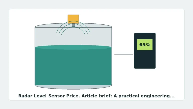
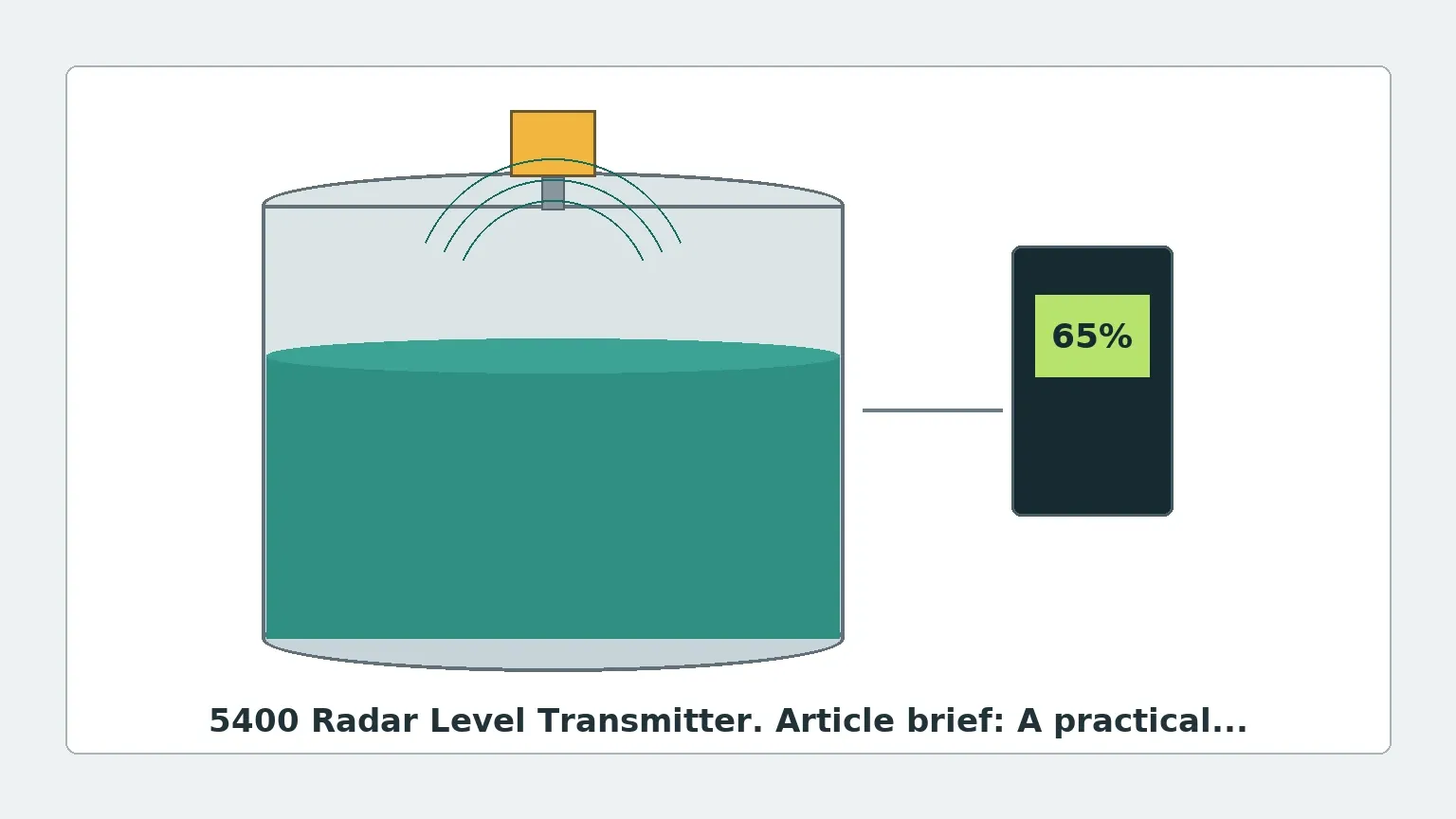
The 5400 radar level transmitter typically operates on the principle of Time-of-Flight. The device emits a high-frequency microwave signal toward the surface of the material. When the signal hits the medium, a portion of the energy is reflected back to the transmitter's antenna. Since microwaves travel at the speed of light, the distance ($D$) is calculated using the formula:
$$D = \frac{c \times t}{2}$$
Where:
* $c$ is the speed of light.
* $t$ is the measured time delay between transmission and reception.
Signal Processing and Echo Filtering
In a real-world industrial tank, the radar signal does not only reflect off the liquid surface. It also reflects off internal structures like agitators, heating coils, and baffles. Advanced transmitters like the 5400 series utilize sophisticated signal processing algorithms to create an "echo curve." This allows the device to distinguish between the true level and "false echoes" caused by tank internals. This capability is vital for maintaining accuracy in cluttered vessels.
2. Key Features of the 5400 Radar Level Transmitter
The 5400 series is specifically engineered for versatility. As a two-wire, non-contacting radar, it is designed to minimize maintenance while maximizing uptime. Key technical characteristics include:
* Dual-Port Technology: Some variants utilize dual-port technology to separate the transmit and receive paths, which enhances the signal-to-noise ratio, particularly in low-dielectric applications.
* High Sensitivity: The ability to detect weak reflections from materials with low dielectric constants ($ε_r$), such as oils or plastic pellets.
* Circular Polarization: This feature helps reduce the impact of reflections from tank walls and improves signal reliability in tall, narrow silos.
* User-Friendly Interface: Modern units often feature graphical displays for on-site echo curve analysis, allowing technicians to troubleshoot without needing external software immediately.
3. Selection Criteria and Technical Specifications
Choosing the correct configuration for a 5400 radar level transmitter requires a deep dive into the process conditions. The following table outlines the primary considerations for antenna selection and frequency choice.
Table 1: Antenna Selection Guide
| Antenna Type | Best For | Temperature/Pressure Limits | Limitations |
| :— | :— | :— | :— |
| Cone (Horn) Antenna | Large tanks, general liquids, and solids. | Up to 250°C / 40 bar | Susceptible to heavy condensation or coating. |
| Process Seal Antenna | Corrosive chemicals, hygienic applications. | Up to 200°C / 25 bar | Fixed beam angle; requires precise nozzle alignment. |
| Parabolic Antenna | Long-range measurements (up to 50m+), low dielectric solids. | High durability | Large footprint; requires a large tank opening. |
| Rod Antenna | Small openings, narrow tanks, acids. | Limited pressure range | Not suitable for high-viscosity liquids that coat the rod. |
Dielectric Constant ($ε_r$) Considerations
The reflectivity of a material is governed by its dielectric constant. Water has a high $ε_r$ (~80), making it an easy target. Conversely, hydrocarbons often have an $ε_r$ between 1.7 and 2.5. When specifying a 5400 series transmitter, the engineer must ensure the device's sensitivity threshold is lower than the $ε_r$ of the medium. If the $ε_r$ is too low, the signal may pass through the material and reflect off the bottom of the tank instead.
4. Installation Guidelines and Constraints
Even the most advanced radar level meter will fail if installed incorrectly. For the 5400 radar level transmitter, several geometric and physical constraints must be observed.
Nozzle Design and Placement
* Nozzle Height: The antenna should ideally extend slightly beyond the bottom of the mounting nozzle to prevent the nozzle edge from creating a large false echo (ringing effect). If the nozzle is very long, a wave-guide or a specific antenna extension may be required.
* Distance from Wall: The transmitter should be mounted at a distance from the tank wall that is at least 1/10th of the tank height. This prevents the beam from reflecting off the wall before reaching the product surface.
* Avoiding Obstructions: The "beam angle" (typically between 8° and 20° depending on antenna size) must be kept clear of agitators, ladders, and inflow streams. If an obstruction is unavoidable, the transmitter's software must be used to "map out" the static echo.
Orientation
For horizontal cylindrical tanks, the transmitter should be mounted at the highest point of the arc, but away from the center if there is a risk of multiple reflections (the "parabolic effect" of the tank roof focusing signals back to the sensor).
5. Industrial Applications for the 5400 Series
Chemical and Petrochemical
In the chemical industry, the 5400 radar level transmitter is frequently used in storage tanks for solvents, acids, and bases. Because it is non-contacting, there is no risk of the instrument being corroded by the medium, provided the wetted parts (the antenna and seals) are made of compatible materials like PTFE or Hastelloy.
Oil and Gas
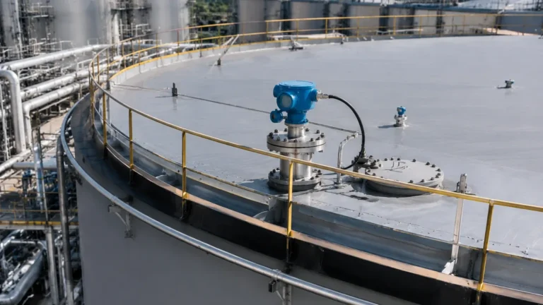
Upstream and downstream operations utilize these transmitters for separator tanks and crude oil storage. The 5400's ability to penetrate heavy vapors and withstand high pressures makes it superior to ultrasonic alternatives in these environments.
Water and Wastewater Treatment
For large-scale basins and chemical dosing tanks, radar provides a maintenance-free alternative to hydrostatic pressure sensors, which can clog, or ultrasonic sensors, which are affected by air temperature gradients and wind.
6. Limitations and Application Risks
While highly versatile, the 5400 radar level transmitter is not a universal solution. Engineers must be aware of the following risks:
1. Heavy Foam: While some radar signals can penetrate light foam, dense, thick foam (like that found in some fermentation processes) can absorb the microwave signal entirely, leading to a "Loss of Echo" (LOE) error.
2. Turbulent Surfaces: Rapidly boiling or agitated liquids can scatter the radar signal. While signal processing can mitigate this, it may result in a lower signal strength and reduced accuracy.
3. Vacuum Conditions: While radar works in a vacuum (unlike ultrasonic sensors), the seals and housing must be rated for vacuum service to prevent air ingress or mechanical failure.
4. Dust and Build-up: In solids applications, extreme dust can attenuate the signal. Furthermore, if the material is sticky and coats the antenna, the signal may be blocked. In these cases, an air purge system is often recommended to keep the antenna face clean.
7. Frequently Asked Questions (FAQ)
Q: How does the 5400 series compare to Guided Wave Radar (GWR)?
A: The 5400 is a non-contacting radar. GWR uses a probe that stays in contact with the medium. Non-contacting radar is preferred when the medium is corrosive, viscous, or when a probe would interfere with an agitator. GWR is better for low-dielectric liquids and interface measurement (e.g., oil over water).
Q: What is the maintenance schedule for a 5400 radar level transmitter?
A: Because there are no moving parts and no contact with the medium, maintenance is minimal. Annual verification of the output against a manual dip-tape measurement is usually sufficient for most ISO quality standards. If the medium is prone to crystallization, the antenna should be inspected periodically for build-up.
Q: Can the 5400 be used for solids?
A: Yes, but with caveats. The 5400 is excellent for large-grain solids. For fine powders with very low dielectric constants, a high-frequency (80 GHz) radar or a parabolic antenna configuration is often more effective at capturing reflections.
Q: Does temperature affect the accuracy of the measurement?
A: Unlike ultrasonic sensors, which depend on the speed of sound (which changes with air temperature), radar uses electromagnetic waves. These are largely unaffected by temperature or pressure changes in the vapor space, making radar much more stable for outdoor or high-temperature process tanks.
8. Conclusion for International Buyers
When sourcing a 5400 radar level transmitter, international buyers should confirm the hazardous area certifications (ATEX, IECEx, FM) required for their specific region. Furthermore, providing the manufacturer with a detailed process data sheet—including the dielectric constant, operating pressure, temperature range, and a tank drawing—is the best way to ensure the instrument is configured correctly at the factory.
By following these engineering principles and selection guidelines, facilities can implement a level measurement solution that provides long-term reliability and high precision. For those looking to compare different high-frequency technologies or antenna configurations, reviewing specialized Radar Level Meters can provide further insights into the latest advancements in signal processing and hardware durability.