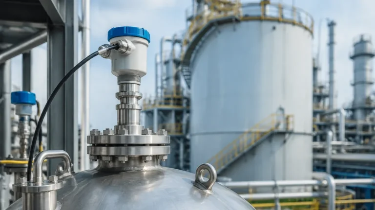
Abb Radar Level Transmitter
Engineering Guide to the ABB Radar Level Transmitter: Principles, Selection, and Application
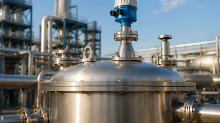
In modern industrial process control, accurate level measurement is the cornerstone of operational safety and efficiency. Among the various technologies available, the abb radar level transmitter has established itself as a high-performance solution for challenging environments ranging from chemical storage to heavy mining. This guide provides a technical overview of radar level measurement principles, selection criteria for specific industrial applications, and the critical installation factors that engineers must consider when deploying Radar Level Meters in the field.
1. Understanding Radar Measurement Principles
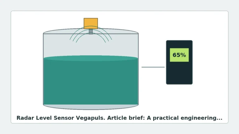
Radar level transmitters operate on the principle of Time Domain Reflectometry (TDR) or Frequency Modulated Continuous Wave (FMCW) technology. To select the correct instrument, it is essential to understand how these signals interact with the process medium.
1.1 Frequency Modulated Continuous Wave (FMCW)
Most modern high-end transmitters, including many in the ABB portfolio, utilize FMCW technology. Unlike pulsed radar, which measures the time it takes for a single pulse to travel to the surface and back, FMCW transmits a continuous signal with a constantly changing frequency.
The difference between the frequency of the transmitted signal and the reflected signal is directly proportional to the distance. This method provides a much higher signal-to-noise ratio, allowing for greater accuracy (often within ±2 mm) and better performance in environments with heavy dust or vapor.
1.2 Pulsed Radar
Pulsed radar transmitters emit short microwave pulses and measure the "time of flight." While generally more energy-efficient and suitable for battery-powered or loop-powered applications, they may struggle with low-dielectric materials or turbulent surfaces compared to FMCW units.
1.3 Guided Wave vs. Non-Contact Radar
* Guided Wave Radar (GWR): Uses a physical probe (cable or rod) to guide the microwave signal. It is ideal for low-dielectric liquids and applications with heavy foam or internal tank obstructions.
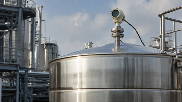
* Non-Contact Radar: Emits signals through the air. This is preferred for corrosive or hygienic applications where the instrument should not touch the process medium.
2. Selection Criteria for Industrial Applications
Choosing an abb radar level transmitter requires a deep dive into the process conditions. One size does not fit all, and the frequency of the device is often the most critical decision point.
2.1 Frequency Considerations (80 GHz vs. 26 GHz)
The move toward higher frequencies has transformed radar measurement.
| Feature | 26 GHz Radar | 80 GHz Radar |
| :— | :— | :— |
| Beam Angle | Wider (approx. 10° – 15°) | Narrow (approx. 3° – 4°) |
| Nozzle Compatibility | Requires larger nozzles | Works with small (1-inch) nozzles |
| Obstruction Handling | May reflect off internal pipes/agitators | Easily avoids internal obstacles |
| Accuracy | Standard (±3 mm to ±5 mm) | High Precision (up to ±1 mm) |
| Dust/Vapor Penetration | Good | Excellent due to signal dynamics |
2.2 Dielectric Constant (εr)
The reflectiveness of a material depends on its dielectric constant. Water has a high εr (~80) and is easy to measure. Hydrocarbons like oil or plastic pellets have low εr (1.5 to 2.5), which results in weaker signal returns. When dealing with low εr materials, engineers must specify high-sensitivity antennas or consider guided wave radar.
3. Installation Constraints and Best Practices
Even the most advanced abb radar level transmitter will fail to perform if installed incorrectly. Precise positioning is required to ensure the microwave beam has a clear path to the product surface.
3.1 Nozzle Geometry
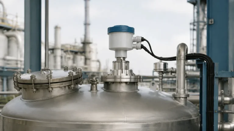
The nozzle height and diameter are critical. If a nozzle is too long or too narrow, the radar signal may reflect off the nozzle wall before reaching the tank interior, creating a "ringing" effect that masks the true level. For 80 GHz transmitters, this risk is minimized, but for lower frequency units, the nozzle should be as short as possible.
3.2 Avoiding Internal Obstructions
Agitators, heating coils, and ladders are common sources of false echoes.
* Beam Path: The signal beam should be kept at least 200 mm (approx. 8 inches) away from the tank wall to prevent interference.
* Agitators: If an agitator is present, the transmitter should be mounted in a position where the beam does not hit the blades directly. Modern software allows for "false echo mapping," where the transmitter learns to ignore static reflections from internal structures.
3.3 The Blind Zone (Blocking Distance)
Every radar transmitter has a "blind zone" directly beneath the antenna (typically 50 mm to 300 mm / 2 to 12 inches). If the liquid level enters this zone, the measurement becomes unreliable. Engineers must ensure the transmitter is mounted high enough that the maximum expected level never enters the blind zone.
4. Application-Specific Risks and Limitations
While radar is highly versatile, certain process conditions present significant challenges that require specialized hardware configurations.
4.1 Heavy Foam and Turbulence
Thick, dense foam can absorb microwave signals, leading to signal loss. In these cases, a Guided Wave Radar or a low-frequency non-contact radar (which penetrates foam better than high-frequency versions) might be necessary. Turbulence caused by filling or mixing can be mitigated using software filtering and damping settings.
4.2 Extreme Temperatures and Pressures
In oil and gas or chemical processing, temperatures can exceed 400°C (752°F) and pressures can reach 400 bar (5800 psi). Transmitters must be equipped with specialized ceramic or PTFE seals and cooling fins to protect the electronics from heat transfer through the process connection.
4.3 Dust and Condensation
In solids measurement (e.g., cement silos or grain elevators), dust can accumulate on the antenna. While 80 GHz signals penetrate dust clouds well, physical buildup on the lens can attenuate the signal. Many ABB units offer air-purge connections to blow away dust and keep the antenna lens clean.
5. Technical Specifications for International Procurement
When sourcing an abb radar level transmitter for a global project, buyers should confirm the following technical parameters to ensure compliance and compatibility:
1. Output Protocol: 4-20 mA HART is standard, but PROFIBUS PA, FOUNDATION Fieldbus, or Modbus may be required for integration into specific DCS (Distributed Control Systems).
2. Hazardous Area Certifications: Ensure the device carries the correct ATEX, IECEx, or FM ratings for the specific zone (e.g., Zone 0, 1, or 2).
3. Wetted Materials: Confirm that the antenna material (316L Stainless Steel, Hastelloy, PTFE, etc.) is chemically compatible with the process medium.
4. Safety Integrity Level (SIL): For safety-critical loops, specify SIL 2 or SIL 3 certified transmitters to comply with IEC 61508/61511 standards.
6. Frequently Asked Questions (FAQs)
Q: Can a radar level transmitter measure through a plastic tank lid?
A: Yes, non-contact radar can penetrate plastic or fiberglass (GRP) tanks. This allows for measurement without cutting a hole in the tank, provided the material has a low dielectric constant and is not too thick.
Q: How does the dielectric constant affect the range of the transmitter?
A: Materials with lower dielectric constants reflect less energy. Therefore, the maximum effective range of a transmitter is reduced when measuring substances like liquid nitrogen or dry powders compared to water-based liquids.
Q: Is maintenance required for non-contact radar?
A: Because there are no moving parts and the instrument does not touch the medium, maintenance is minimal. Periodic verification of the signal strength and cleaning of the antenna (if an air purge is not used) are the only typical requirements.
Q: What is the difference between a radar level transmitter and an ultrasonic sensor?
A: Ultrasonic sensors use sound waves, which are affected by air temperature, pressure, and vacuum. Radar uses electromagnetic waves, which travel at the speed of light and are unaffected by changes in the gas space above the liquid, making radar far more reliable in varying process conditions.
Conclusion
The implementation of an abb radar level transmitter offers a robust solution for complex level measurement tasks. By understanding the physics of FMCW technology and carefully evaluating the physical constraints of the vessel—such as nozzle height, internal obstructions, and the dielectric properties of the medium—engineers can achieve high-precision monitoring. For more information on selecting the right technology for your specific industrial environment, you can explore various Radar Level Meters designed for global industrial standards. Proper selection not only ensures process safety but also significantly reduces long-term maintenance costs through reliable, non-contact sensing.