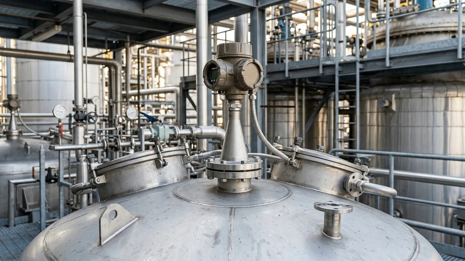
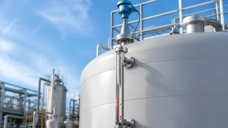
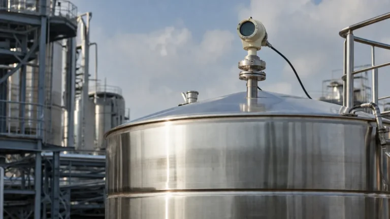
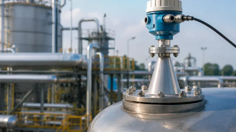
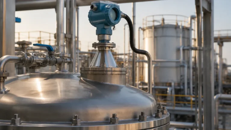
Ametek Radar Level Transmitter
In the complex landscape of industrial process control, selecting the right instrumentation is a critical decision that impacts safety, efficiency, and profitability. Among the various technologies available for liquid and solid level monitoring, the ametek radar level transmitter stands out as a sophisticated solution designed to handle challenging environments. This guide provides a comprehensive engineering reference for understanding radar technology, focusing on the principles, selection criteria, and installation requirements necessary for successful deployment in B2B industrial applications.
Understanding Radar Level Measurement Principles
Before selecting a specific Radar Level Meters solution, it is essential to understand the physics governing these devices. Radar level transmitters operate on the principle of Time of Flight (ToF). The device emits an electromagnetic wave—typically in the microwave frequency range—which travels through the tank headspace, reflects off the surface of the material being measured, and returns to the sensor.
There are two primary methods used in modern radar transmitters:
1. Pulse Radar (Non-Contact)
Pulse radar transmitters emit a short burst of energy and measure the time it takes for the pulse to return. Because the speed of light is constant, the distance to the product surface can be calculated using the formula:
*Distance = (Speed of Light × Time of Flight) / 2*.
2. FMCW (Frequency Modulated Continuous Wave)
FMCW radar, often found in high-precision instruments like the Ametek Drexelbrook series, transmits a continuous signal with a constantly changing frequency. The difference in frequency between the transmitted signal and the reflected signal is proportional to the distance. FMCW is generally preferred for applications requiring high accuracy and better signal-to-noise ratios in turbulent conditions.
3. Guided Wave Radar (GWR)
Unlike non-contact radar, GWR utilizes a physical probe (rod or cable) to guide the microwave signal to the surface. This method is highly effective for materials with low dielectric constants or in tanks with heavy foam and steam, as the signal is concentrated along the waveguide rather than dispersing through the air.
Technical Features of Ametek Radar Level Transmitters
Ametek, particularly through its Drexelbrook brand, provides a range of radar transmitters engineered for high-performance level sensing. These devices are characterized by their ability to ignore internal tank obstructions and provide reliable data even in the presence of vapors or dust.
Key technical attributes often include:
* High-Frequency Operation: Many modern units operate at 80 GHz, allowing for smaller antenna sizes and narrower beam angles, which reduces interference from tank walls and internal structures.
* Dual-Compartment Housing: Separates the electronics from the wiring terminals, enhancing durability in corrosive environments.
* Advanced Signal Processing: Algorithms designed to filter out "false echoes" caused by agitators, ladders, or baffles.
Selection Criteria for Industrial Applications
Choosing the correct ametek radar level transmitter requires a deep dive into the process conditions. Engineers must evaluate several variables to ensure the chosen instrument will function within its specified accuracy limits.
Dielectric Constant ($ε_r$)
The dielectric constant of the medium is the most significant factor in radar measurement. It determines how much energy is reflected back to the sensor.
* High $ε_r$ (>10): Water-based liquids reflect signals strongly, making measurement straightforward.
* Low $ε_r$ (1.4 to 4): Hydrocarbons and solvents reflect less energy. In these cases, Guided Wave Radar or high-sensitivity non-contact radar is required.
Process Temperature and Pressure
Standard radar sensors are often rated for temperatures up to 150°C (302°F) and pressures up to 40 bar (580 psi). However, specialized versions with ceramic seals and cooling fins are available for high-temperature reactors or high-pressure liquefied gas storage.
Selection Table: Radar Technology Comparison
| Feature | Non-Contact Radar (80 GHz) | Guided Wave Radar (GWR) |
| :— | :— | :— |
| Best Use Case | Corrosive liquids, tall silos | Low dielectric liquids, foaming tanks |
| Installation | Top-mounted, no contact | Probe must reach bottom of tank |
| Maintenance | Extremely low (no moving parts) | Low, but probe may need cleaning |
| Obstruction Sensitivity | Low (narrow beam) | High (signal stays on probe) |
| Max Range | Up to 100m (328 ft) | Up to 30m (98 ft) |
Installation Considerations and Best Practices
Even the most advanced ametek radar level transmitter will fail to perform if installation guidelines are ignored. Proper placement is the difference between a stable signal and constant troubleshooting.
1. Nozzle Height and Diameter: The antenna should ideally extend slightly below the mounting nozzle to prevent signal ringing within the nozzle itself. For 80 GHz units, smaller nozzles are acceptable, but for lower frequency units (6 GHz or 26 GHz), larger nozzles are required to accommodate the horn antenna.
2. The "Dead Zone" (Blocking Distance): Every radar has a minimum distance it cannot measure (usually 50mm to 200mm from the antenna). Ensure the maximum fill level does not enter this zone.
3. Avoid the Center: Never mount a radar transmitter in the exact center of a domed tank, as this can cause multiple reflections to converge at the sensor, creating a "false high" reading.
4. Agitators and Obstructions: If the tank has an agitator, the radar should be mounted such that the beam does not hit the blades. If this is unavoidable, use the software's "false echo mapping" feature to teach the device to ignore the stationary or rotating interference.
Application Risks and Limitations
While radar is a robust technology, it is not a universal solution. Engineers should be aware of the following risks:
* Heavy Foam: Thick, dense foam (like shaving cream) can absorb the radar signal entirely, leading to a "Loss of Echo." In these instances, Guided Wave Radar is the preferred alternative.
* Vapor and Condensation: While radar is generally unaffected by vapor, extreme condensation on the antenna lens can attenuate the signal. Choosing a PTFE-coated lens or a dripping-cone antenna design helps mitigate this.
* Solid Angle of Repose: In solids measurement (e.g., grain or plastic pellets), the material does not sit flat. The radar beam may reflect away from the sensor if the angle of the pile is too steep. High-frequency 80 GHz radar with a narrow beam is best suited for these applications.
Frequently Asked Questions (FAQs)
Q: Can an ametek radar level transmitter measure interface levels?
A: Yes, Guided Wave Radar (GWR) is particularly effective for interface measurement (e.g., oil over water). The signal reflects off the upper liquid layer and continues through to reflect off the lower liquid layer, provided the upper layer has a lower dielectric constant.
Q: How does dust affect the measurement?
A: Non-contact radar is largely unaffected by dust, making it superior to ultrasonic sensors in silos. However, in extremely dusty environments, a purge connection may be used to keep the antenna lens clean.
Q: Is calibration required frequently?
A: No. Radar is a solid-state technology with no moving parts. Once the tank geometry and dielectric parameters are set, the device typically requires only periodic verification rather than full recalibration.
Conclusion: Buyer's Confirmation Checklist
When sourcing an ametek radar level transmitter or a similar Radar Level Meters solution, international buyers and project engineers should confirm the following data points with the manufacturer:
1. Material Safety Data Sheet (MSDS): Confirm the dielectric constant of the process medium at operating temperature.
2. Tank Drawings: Provide dimensions, nozzle locations, and a list of internal obstructions.
3. Hazardous Area Ratings: Specify if ATEX, IECEx, or FM approvals are required for explosive atmospheres.
4. Output Protocol: Ensure compatibility with existing control systems (4-20mA HART, Profibus, or Foundation Fieldbus).
By following these technical guidelines and understanding the fundamental measurement principles, industrial operators can ensure long-term reliability and accuracy in their level monitoring systems. Whether dealing with corrosive chemicals in water treatment or high-temperature hydrocarbons in oil and gas, radar technology remains a cornerstone of modern industrial automation.