Contactless Radar Level Transmitter
Contactless Radar Level Transmitter: Engineering Principles and Selection Guide
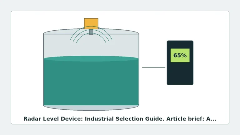
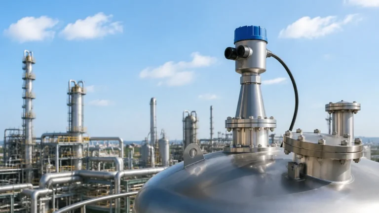
In the landscape of industrial automation, the demand for high-precision, low-maintenance measurement solutions has led to the widespread adoption of the contactless radar level transmitter. Unlike traditional mechanical or contact-based sensors, these instruments utilize microwave technology to determine the distance to a product surface without physical interaction. This engineering guide explores the fundamental principles, technical selection criteria, and installation best practices for Radar Level Meters in B2B process environments.
1. Measurement Principles of Radar Technology
To effectively implement a contactless radar level transmitter, it is essential to understand the two primary methods of microwave measurement: Pulse Radar and Frequency Modulated Continuous Wave (FMCW).
1.1 Pulse Radar (Time of Flight)
Pulse radar systems emit high-frequency microwave pulses toward the medium. These pulses travel at the speed of light, reflect off the surface of the material, and return to the sensor antenna. The instrument measures the "Time of Flight" (ToF)—the interval between transmission and reception.
* Formula: $D = (c \times t) / 2$
* Where $D$ is the distance, $c$ is the speed of light, and $t$ is the measured time.
While robust, pulse radar typically offers lower resolution compared to FMCW and is often used in applications where extremely high precision is less critical than cost-efficiency.
1.2 Frequency Modulated Continuous Wave (FMCW)
Modern high-end Radar Level Meters frequently utilize FMCW technology. Instead of discrete pulses, the transmitter emits a continuous signal with a frequency that changes linearly over time (a frequency sweep). When the reflected signal is received, it is compared to the signal being transmitted at that exact moment. The difference in frequency ($Δf$) is directly proportional to the distance.
FMCW provides superior signal-to-noise ratios and higher accuracy, making it the preferred choice for measuring liquids with low dielectric constants or in tanks with significant internal turbulence.
2. Technical Selection Criteria
Selecting the correct contactless radar level transmitter requires an analysis of the process medium, the vessel geometry, and the environmental conditions. The following table outlines the technical differences between common frequency bands used in industrial radar.
Table 1: Comparison of Radar Frequency Bands
| Feature | 6 GHz – 10 GHz (C-Band) | 24 GHz – 26 GHz (K-Band) | 76 GHz – 81 GHz (W-Band) |
| :— | :— | :— | :— |
| Beam Angle | Wide (approx. 20°-30°) | Medium (approx. 8°-12°) | Narrow (approx. 3°-4°) |
| Sensitivity to Foam | Low (Better penetration) | Moderate | High (Reflects off foam) |
| Accuracy | ± 5 mm to 10 mm | ± 2 mm to 3 mm | ± 1 mm |
| Antenna Size | Large | Medium | Small / Compact |
| Best Application | Heavy steam, turbulence | Standard process tanks | Tall silos, narrow nozzles |
2.1 The Role of the Dielectric Constant (εr)
The dielectric constant of the medium is the most critical factor in signal reflection. Materials with high εr (e.g., water, εr ≈ 80) reflect signals strongly. Hydrocarbons and oils (e.g., εr ≈ 1.9 to 2.1) reflect much less energy. When selecting a contactless radar level transmitter, engineers must ensure the device's sensitivity threshold is lower than the reflection profile of the medium.
3. Antenna Design and Material Compatibility
The antenna is the interface between the electronics and the process. Its design dictates the beam focus and resistance to corrosion.
* Horn Antennas: Common for standard liquid applications. Available in stainless steel (316L) or Hastelloy for corrosive environments.
* Drip-off / Lens Antennas: Constructed from PTFE or PFA, these are designed for hygienic applications or environments where condensation and buildup occur. The convex shape allows droplets to run off, preventing signal attenuation.
* Parabolic Antennas: Used primarily for long-range measurements in large solids silos (up to 100 meters), providing a highly focused beam to minimize interference from vessel walls.
4. Installation Considerations and Constraints
Even the most advanced Radar Level Meters will fail if installed incorrectly. Engineering teams must adhere to specific spatial constraints to ensure a clear "line of sight" for the microwave beam.
4.1 Beam Path and Obstructions
The radar beam spreads as it travels. Any internal structure—such as heating coils, ladders, or agitators—within this beam path will create a "false echo." While modern software allows for "False Echo Suppression" (mapping out static reflections), it is best practice to install the sensor at least 300 mm to 500 mm away from the tank wall to avoid side-lobe interference.
4.2 Nozzle Geometry
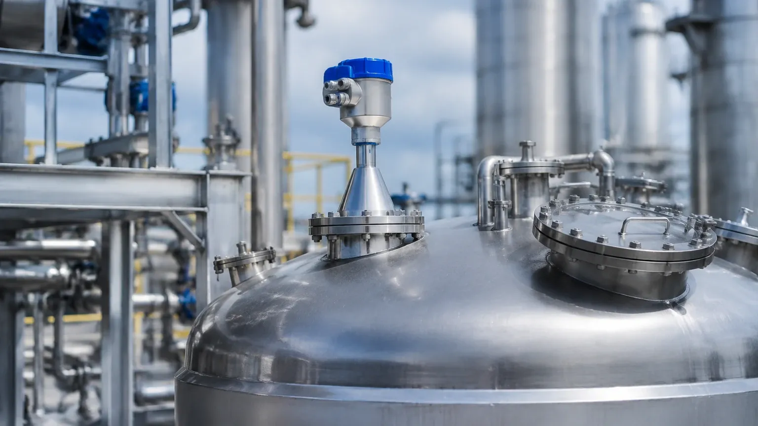
The mounting nozzle should be as short as possible. If the nozzle is too long or narrow, the radar signal may reflect off the nozzle's internal edges before reaching the medium. For high-frequency 80 GHz transmitters, the narrow beam allows for installation in smaller nozzles (DN25 or DN50), whereas 26 GHz units typically require larger openings.
4.3 Dead Zones (Blocking Distance)
Every contactless radar level transmitter has a "dead zone" or "upper blocking distance" directly beneath the antenna (typically 50 mm to 200 mm). Measurement is not possible in this zone. If the tank is frequently filled to the brim, the transmitter should be mounted on a stand-off pipe to elevate the antenna above the maximum fill level.
5. Application-Specific Risks and Mitigations
5.1 Heavy Dust and Solids
In solids measurement (e.g., cement or grain), the surface is rarely flat. It forms cones and valleys. High-frequency 80 GHz radar is superior here because its narrow beam can target a specific point on the material surface, and its high dynamic range can process the weak, scattered signals characteristic of bulk solids.
5.2 Agitation and Turbulence
Surface ripples caused by mixers can scatter radar signals. To mitigate this, engineers can use a stilling well (a bypass pipe) to create a calm surface for the radar to measure. Alternatively, selecting an FMCW-based transmitter with advanced signal processing can help filter out the "noise" created by turbulent surfaces.
5.3 High Pressure and Temperature
Standard radar units operate up to 130°C. For extreme applications (e.g., boiler feed water or chemical reactors), specialized high-temperature versions with ceramic seals and cooling fins are required to protect the electronics. Pressure ratings can reach up to 40 MPa (400 Bar) in specialized configurations.
6. Maintenance and Calibration
One of the primary advantages of the contactless radar level transmitter is the lack of moving parts, which significantly reduces maintenance requirements. However, periodic verification is still necessary.
* Visual Inspection: Check the antenna for coating or buildup, especially in sticky or crystallizing media.
* Signal Quality Monitoring: Most digital transmitters provide a "Signal-to-Noise Ratio" (SNR) or "Echo Amplitude" value. A steady decline in this value over time may indicate antenna fouling or electronic degradation.
* Field Calibration: Verification can be performed using a handheld communicator (HART) or via Bluetooth/PC software. It is recommended to perform a full-loop check annually to ensure the 4-20mA or digital output matches the physical level.
7. Frequently Asked Questions (FAQ)
Q: Can a contactless radar level transmitter measure through a plastic tank lid?
A: Yes. Since microwaves can penetrate non-conductive materials like plastics (PE, PP, PVC) and glass, the sensor can be mounted outside the tank to measure the level through the roof, provided the material is not too thick or reinforced with carbon fiber.
Q: How does vacuum affect radar measurement?
A: Unlike ultrasonic sensors, which require air to transmit sound, radar waves travel through a vacuum without any loss of speed or accuracy. This makes radar the ideal choice for vacuum distillation columns.
Q: Is radar affected by changes in gas composition or density?
A: Generally, no. The speed of light is largely independent of the gas phase above the liquid, unlike the speed of sound. This makes radar much more stable than ultrasonic technology in applications involving heavy vapors or nitrogen blanketing.
Q: What is the minimum dielectric constant required?
A: Most high-performance Radar Level Meters can measure materials with a dielectric constant (εr) as low as 1.4. For materials below this (like liquid hydrogen), guided wave radar or specialized high-sensitivity contactless units are necessary.
8. Summary for International Buyers
When procuring a contactless radar level transmitter, international buyers should provide the following data to the manufacturer to ensure a correct fit:
1. Medium Name and Dielectric Constant: To determine signal strength.
2. Process Temperature and Pressure: For seal and housing selection.
3. Vessel Height and Shape: To determine the required frequency and antenna type.
4. Nozzle Dimensions: To ensure the beam clears the mounting hardware.
5. Required Approvals: (e.g., ATEX/IECEx for hazardous areas, SIL2 for safety systems).
By following these technical guidelines, engineering teams can implement reliable, high-precision level measurement solutions that reduce downtime and improve process efficiency across a wide range of industrial sectors.