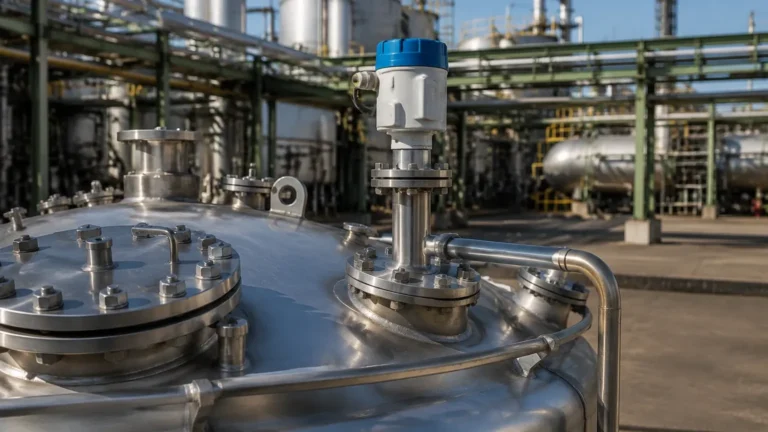
Eip Radar Level Transmitter
Understanding the EIP Radar Level Transmitter in Industrial Process Control
In the landscape of industrial automation, precise level measurement is a fundamental requirement for safety, inventory management, and process efficiency. Among the various technologies available, the eip radar level transmitter stands out as a sophisticated solution for challenging environments. Utilizing high-frequency microwave signals combined with advanced signal processing, these instruments provide non-contact measurement that remains largely unaffected by changes in temperature, pressure, or the presence of dust and vapors.
For engineers and procurement professionals, selecting the right instrumentation requires a deep dive into the underlying physics of radar technology and the specific software algorithms—such as Echo Image Processing (EIP)—that allow these devices to distinguish between a true material surface and parasitic reflections from tank internals.
Measurement Principles of Radar Technology
Before selecting an eip radar level transmitter, it is essential to understand how radar energy interacts with the process media. Industrial radar level meters generally operate on one of two primary principles: Pulse Radar or Frequency Modulated Continuous Wave (FMCW).
Pulse Radar (Time-of-Flight)
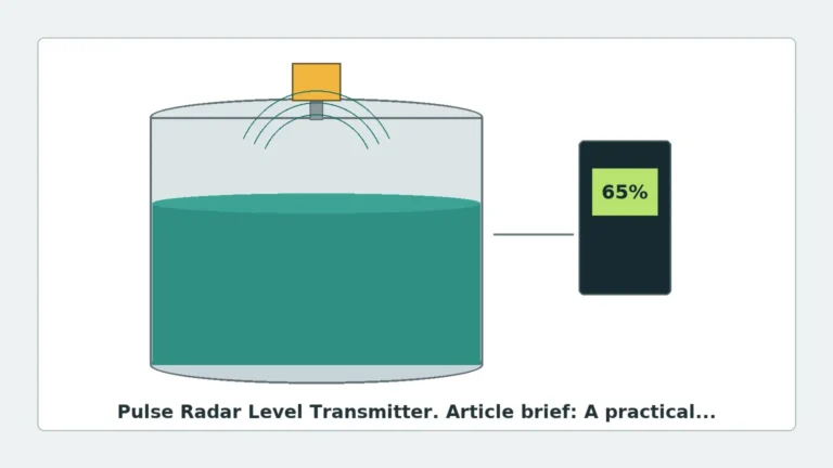
In pulse radar systems, the transmitter emits a short microwave pulse toward the product surface. The pulse reflects off the surface and returns to the antenna. The instrument measures the time-of-flight (ToF) from emission to reception. Since the speed of light is constant, the distance is calculated as:
*Distance = (Speed of Light × Time-of-Flight) / 2*
FMCW (Frequency Modulated Continuous Wave)
FMCW radar transmits a continuous signal with a constantly changing frequency. When the reflected signal is received, it is compared to the signal being transmitted at that exact moment. The frequency difference between the transmitted and received signals is directly proportional to the distance. FMCW is often preferred for high-precision applications due to its superior signal-to-noise ratio.
The Role of EIP (Echo Image Processing)
The "EIP" in an eip radar level transmitter refers to the advanced signal processing algorithms used to analyze the "echo curve." In a real-world industrial tank, the radar signal does not just hit the liquid; it hits agitators, ladders, heating coils, and weld seams. EIP software creates a digital map of the tank's interior, identifying and "masking" these static obstacles. This ensures that the transmitter tracks only the dynamic level of the product, even in complex geometries.
Technical Selection Criteria
Choosing the correct Radar Level Meters involves matching the instrument's frequency and antenna design to the specific properties of the media. The following table provides a practical engineering reference for selection.
Selection Comparison Table
| Feature | 26 GHz Radar | 80 GHz Radar | Guided Wave Radar (GWR) |
| :— | :— | :— | :— |
| Primary Use | General liquids/solids | Narrow tanks, high precision | Low dielectric media, foam |
| Beam Angle | Moderate (8° to 20°) | Narrow (3° to 6°) | N/A (signal follows probe) |
| Dust/Vapor Resistance | High | Excellent | Moderate |
| Accuracy | ±3 mm to ±5 mm | ±1 mm | ±2 mm |
| Dielectric Constant (εr) | > 1.9 | > 1.4 | > 1.2 |
| Max Range | Up to 30m – 70m | Up to 120m | Up to 30m (probe limited) |
The Dielectric Constant (εr) Constraint
The reflectivity of a material is determined by its dielectric constant. Materials with high dielectric constants (e.g., water, εr ≈ 80) reflect radar signals very well. Hydrocarbons and oils (εr ≈ 2.0) are much less reflective. When using an eip radar level transmitter on low-dielectric materials, a larger antenna or a higher frequency (80 GHz) is often required to ensure a reliable return signal.
Installation Considerations and Constraints
Even the most advanced eip radar level transmitter will fail if installed incorrectly. Engineering teams must adhere to specific mechanical boundaries to prevent signal interference.
1. The Dead Zone (Blocking Distance): Every radar has a minimum distance near the antenna where measurement is not possible. This is typically between 0.1m and 0.5m. The maximum fill level must never enter this zone.
2. Nozzle Dimensions: The mounting nozzle should be as short and wide as possible. If the nozzle is too long or narrow, the radar signal will bounce off the interior of the nozzle, creating a large "ringing" echo that can mask the true level near the top of the tank.
3. Beam Path Obstructions: The "beam angle" defines a cone-shaped area. No structural elements (pipes, braces, or mixers) should enter this cone. If they do, the EIP software must be used to perform a "false echo suppression" or "static mapping" during commissioning.
4. Positioning on the Tank: The transmitter should typically be mounted at 1/6th to 1/4th of the tank diameter from the wall. It should never be mounted in the center of a domed-roof tank, as this can cause multiple reflections to converge at the antenna, leading to signal errors. Similarly, avoid mounting directly over the filling inlet to prevent interference from the falling product.
Application Risks and Limitations
While radar is highly versatile, certain process conditions present risks to measurement stability:
* Heavy Foam: Dense, thick foam can absorb radar signals entirely, leading to a "loss of echo." In such cases, Guided Wave Radar or specialized low-frequency radar may be more effective.
* Extreme Turbulence: Rapidly moving liquid surfaces can scatter the radar signal. While EIP algorithms can smooth out these fluctuations using damping settings, extreme cases may require a stilling well or bypass chamber.
* Condensation and Buildup: While many eip radar level transmitters feature PTFE-faced antennas to shed moisture, heavy crystalline buildup can eventually attenuate the signal. Periodic inspection or the use of an integrated air-purge system for cleaning may be necessary.
Practical Maintenance and Commissioning
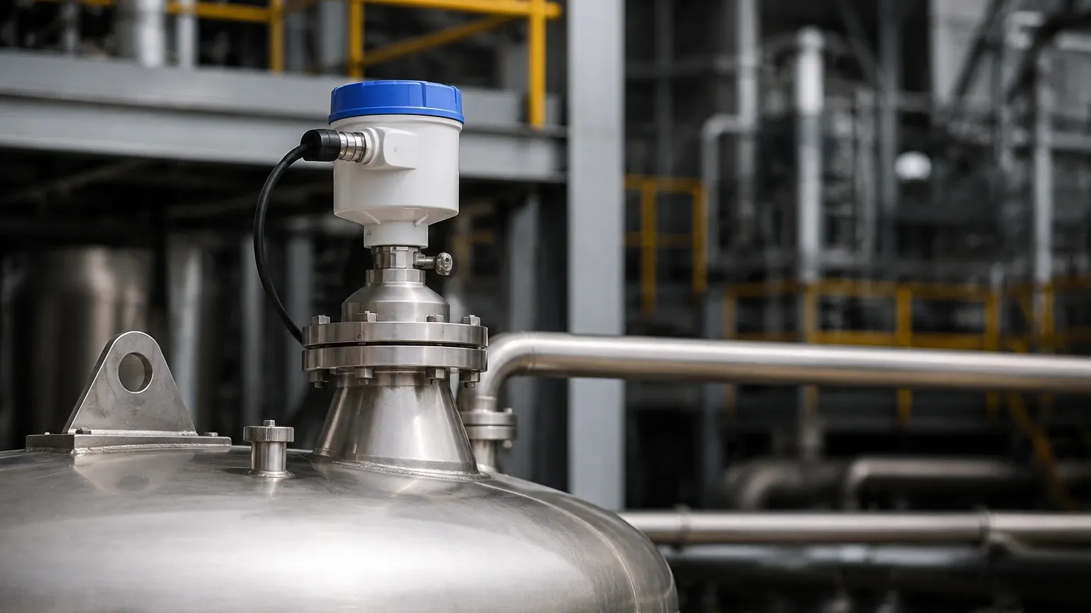
Commissioning an eip radar level transmitter involves more than just wiring the 4-20mA loop. Engineers should follow a standardized checklist:
* Empty Tank Mapping: If possible, perform a signal scan when the tank is empty. This allows the EIP software to record all internal reflections and store them as a baseline.
* Dielectric Adjustment: Ensure the software is configured for the correct dielectric range of the medium. Setting this too high on a low-dielectric fluid can result in the radar "looking through" the product to the tank bottom.
* Vessel Height Calibration: Confirm that the "zero point" (usually the bottom of the tank or the end of the discharge pipe) is accurately entered into the transmitter's parameters.
Frequently Asked Questions (FAQ)
Q: Can an eip radar level transmitter measure through a plastic tank wall?
A: Yes. Since microwaves can penetrate non-conductive materials, radar can often measure the level inside a plastic or fiberglass tank without the need for a process penetration, provided the wall thickness is not excessive and the material is not carbon-filled.
Q: What is the difference between 26GHz and 80GHz radar?
A: 80GHz radar uses a much shorter wavelength, which allows for a smaller antenna and a much narrower beam. This makes it ideal for tall, narrow silos or tanks with many internal obstructions. 26GHz is often more robust in applications with heavy dust or steam.
Q: How does temperature affect radar measurement?
A: Unlike ultrasonic sensors, which depend on the speed of sound (which varies with air density/temperature), radar waves travel at the speed of light. Therefore, temperature changes in the vapor space have a negligible effect on radar accuracy.
Q: Is a stilling well necessary for radar?
A: A stilling well is used to protect the measurement from turbulence and foam. It is also used when the dielectric constant is very low, as the pipe acts as a waveguide to concentrate the signal energy. For most standard liquid applications with an eip radar level transmitter, a stilling well is not required.
Conclusion
The integration of eip radar level transmitter technology into industrial processes provides a level of reliability that was previously difficult to achieve with contact-based methods. By leveraging Echo Image Processing, these devices navigate the complexities of modern industrial vessels, offering clear and accurate data for automation systems. When selecting Radar Level Meters, engineers must balance frequency, antenna design, and installation geometry to ensure long-term performance. As a professional manufacturer, Welk continues to provide customized solutions that address these specific engineering challenges across the water treatment, chemical, and oil and gas sectors.