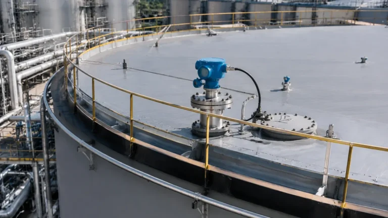
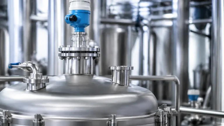
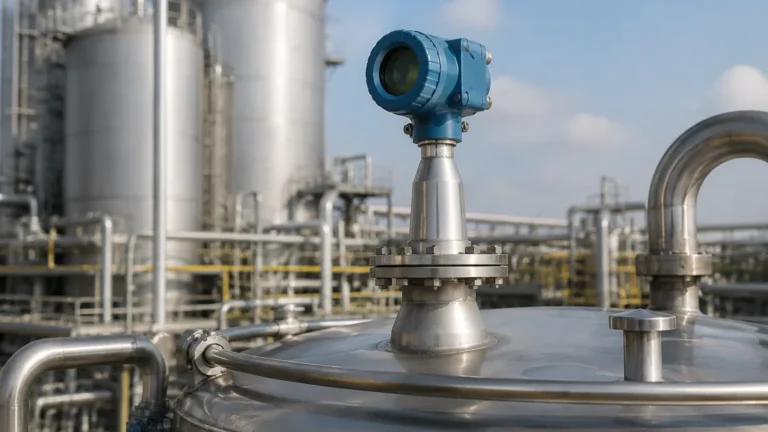
Guided Radar Level Transmitter
Guided Radar Level Transmitter: A Technical Engineering Guide to TDR Measurement
In the field of industrial process control, accurate level measurement is critical for operational safety, inventory management, and process efficiency. Among the various technologies available, the guided radar level transmitter—also known as Guided Wave Radar (GWR)—has emerged as one of the most versatile and reliable solutions for both liquid and solid applications. By utilizing Time Domain Reflectometry (TDR) technology, these instruments overcome many of the limitations faced by non-contact ultrasonic or traditional pressure-based sensors.
This guide provides a comprehensive technical overview of guided radar technology, explaining its operating principles, probe selection criteria, installation requirements, and the specific factors that international procurement engineers must consider when specifying Radar Level Meters for complex industrial environments.
1. Measurement Principle: Time Domain Reflectometry (TDR)
The fundamental technology behind a guided radar level transmitter is Time Domain Reflectometry (TDR). Unlike non-contact radar, which broadcasts electromagnetic waves through the air, GWR directs low-energy, high-frequency electromagnetic pulses along a physical conductor (the probe).
How the Measurement Cycle Works
1. Pulse Emission: The transmitter electronics generate a micro-pulse that travels down the probe at the speed of light.
2. Reflection: When the pulse encounters a medium with a different dielectric constant ($ε_r$) than the one it is currently traveling through (usually air or vapor), a portion of the pulse energy is reflected back toward the transmitter.
3. Signal Processing: The electronics measure the time of flight between the emission of the pulse and the reception of the reflected signal. Since the speed of light is constant, the distance to the product surface is calculated using the formula: $D = (c × t) / 2$, where $c$ is the speed of light and $t$ is the measured time.
4. Level Calculation: By knowing the total tank height (the zero point), the device subtracts the measured distance from the total height to determine the actual level of the material.
The Role of the Dielectric Constant
The dielectric constant ($ε_r$) of the medium is the most critical factor in GWR measurement. It determines how much energy is reflected. A high dielectric material, such as water ($ε_r ≈ 80$), produces a very strong reflection. Low dielectric materials, such as hydrocarbons or oils ($ε_r ≈ 1.4$ to $2.5$), produce much weaker reflections. Modern guided radar level transmitters are designed with sensitive electronics capable of detecting these faint signals, making them suitable for a wide range of chemical and petrochemical applications.
2. Probe Types and Selection Criteria
The performance of a guided radar level transmitter is heavily dependent on the type of probe used. The probe acts as the waveguide, and its geometry must be matched to the medium and the vessel constraints.
Single Rod or Cable Probes
These are the most common probe types. They consist of a single stainless steel rod (for shorter distances, typically up to 6 meters) or a flexible cable (for tall silos or tanks, up to 30 meters or more).
* Advantages: Less prone to buildup; easier to clean; cost-effective.
* Best For: Liquids with moderate to high dielectric constants and applications where the probe might be subject to coating.
Twin Rod or Cable Probes
Twin probes consist of two parallel conductors. The electromagnetic field is concentrated between the two probes, which increases the signal strength.
* Advantages: Better performance in lower dielectric liquids compared to single rods.
* Limitations: Highly susceptible to bridging; if material gets stuck between the two rods, it will cause a false high-level reading.
Coaxial Probes
A coaxial probe consists of a central rod inside an outer perforated tube. This design offers the highest signal-to-noise ratio because the electromagnetic pulse is completely contained within the tube.
* Advantages: Not affected by tank internal structures (ladders, agitators); ideal for very low dielectric liquids ($ε_r > 1.4$); works well in turbulent surfaces.
* Limitations: Only suitable for clean, low-viscosity liquids. Any particulate or viscous coating will clog the tube.
Comparison Table: Probe Selection
| Feature | Single Rod/Cable | Twin Rod/Cable | Coaxial Probe |
| :— | :— | :— | :— |
| Max Range | Up to 60m (cable) | Up to 30m | Up to 6m |
| Min Dielectric (ε_r) | ≥ 1.6 (with bypass) | ≥ 1.9 | ≥ 1.4 |
| Buildup Resistance | Excellent | Poor | Very Poor |
| Obstruction Immunity | Moderate | High | Excellent |
| Application | Corrosive liquids, solids | Liquefied gases | Clean oils, solvents |
3. Interface Measurement Capability
One of the unique advantages of the guided radar level transmitter is its ability to measure both the total level and the interface level between two immiscible liquids (e.g., oil over water).
When the pulse hits the upper liquid layer (the low dielectric medium), a portion of the signal is reflected (the total level). The remaining energy continues through the upper liquid and reflects off the lower liquid layer (the high dielectric medium), providing the interface level. For successful interface measurement, the upper layer must have a lower dielectric constant than the lower layer, and the upper layer must be thick enough (typically >100mm) for the transmitter to distinguish between the two pulses.
4. Installation Considerations and Constraints
While GWR is robust, improper installation can lead to signal loss or measurement errors. Engineering teams should adhere to the following guidelines:
Nozzle Geometry
The diameter and height of the mounting nozzle can affect the signal at the top of the tank. In a guided radar level transmitter, the "Upper Dead Zone" (or blocking distance) is the area near the process connection where measurement is not possible. Engineers must ensure the maximum liquid level does not enter this zone, or use a nozzle that allows the probe to be recessed.
Internal Obstructions
For single rod or cable probes, the signal radiates outward from the probe. Therefore, the probe must be installed at a certain distance from the tank wall and any internal structures like agitators, heating coils, or ladders. A general rule is to maintain a minimum clearance of 300mm (12 inches) from any metal object.
Cable Tensioning
In tall silos containing solids, the downward pull (friction) on a cable probe can be immense, reaching several tons. The roof of the tank must be structurally reinforced to handle these loads, and the cable should be anchored at the bottom only if the manufacturer’s tensioning instructions are strictly followed to prevent mechanical failure.
Bypass Chambers and Stilling Wells
In applications with heavy turbulence, foam, or internal obstructions, GWR probes are often installed inside a bypass chamber or a stilling well. This provides a calm surface for measurement and allows the use of single rod probes in environments where they would otherwise be unsuitable.

5. Limitations and Application Risks
Despite its versatility, the guided radar level transmitter is not a universal solution. Engineers must be aware of the following limitations:
1. Probe Coating and Buildup: While GWR is more resistant to coating than ultrasonic sensors, excessive buildup of conductive or thick viscous material on the probe can attenuate the signal or cause "ghost" reflections.
2. Mechanical Stress: In heavy solids applications (like large grain silos or mineral ore bins), the lateral forces on a rod probe can bend or break it. Cable probes are preferred here, but they are still subject to tensile stress.
3. Minimum Dielectric Requirements: If the medium has an extremely low dielectric constant (below 1.4), the reflection may be too weak to detect without a coaxial probe or a bypass pipe.
4. Corrosion: Because the probe is in direct contact with the medium, material compatibility is vital. Standard probes are 316L stainless steel, but aggressive chemicals may require PTFE, Hastelloy, or Monel coatings.
6. Comparison: Guided vs. Non-Contact Radar
When selecting Radar Level Meters, engineers often choose between Guided Wave (GWR) and Non-Contact (Pulse or FMCW) radar.
* Foam: GWR is generally superior in foamy applications because the probe guides the signal through the foam to the liquid surface. Non-contact radar signals are often absorbed or scattered by thick foam.
* Vapor and Dust: Both technologies handle vapor well, but GWR is often more reliable in extremely dusty environments (like cement silos) because the signal is concentrated along the probe.
* Tank Geometry: GWR is ideal for narrow tanks or tanks with many internal obstructions, as the pulse is confined to the probe. Non-contact radar requires a clear "line of sight."
* Maintenance: Non-contact radar has the advantage of no moving parts and no contact with the medium, reducing cleaning requirements.
7. Frequently Asked Questions (FAQ)
Q: Can a guided radar level transmitter be used in high-pressure/high-temperature applications?
A: Yes. GWR transmitters can be engineered with specialized ceramic seals and cooling fins to operate in environments exceeding 400°C and pressures up to 400 bar, making them ideal for boiler drum level and refinery separators.
Q: Does the probe need to be grounded?
A: The transmitter housing must be properly grounded to the vessel to ensure a stable reference for the TDR pulse. In non-metallic tanks, a dual-rod probe or a large metal flange/grounding plate is required.
Q: Can I cut the probe to length in the field?
A: Most rod and cable probes can be shortened in the field. However, the transmitter's configuration software must be updated with the new probe length to maintain accuracy. Coaxial probes are generally not field-cuttable.
Q: How does agitation affect the measurement?
A: While GWR is more stable than ultrasonic sensors in turbulent conditions, extreme agitation can cause the probe to swing and potentially touch the tank wall or internal structures. In such cases, the probe should be secured at the bottom or housed in a stilling well.
Conclusion
The guided radar level transmitter represents a robust, high-precision solution for the most challenging industrial level measurement tasks. By understanding the dielectric properties of the medium and selecting the appropriate probe geometry, engineers can implement a system that provides reliable data even in the presence of foam, vapor, and turbulence. When specifying these instruments, always verify the chemical compatibility of the wetted parts and the structural integrity of the vessel to ensure long-term performance in demanding B2B industrial environments.