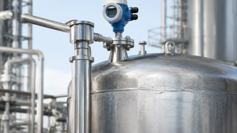
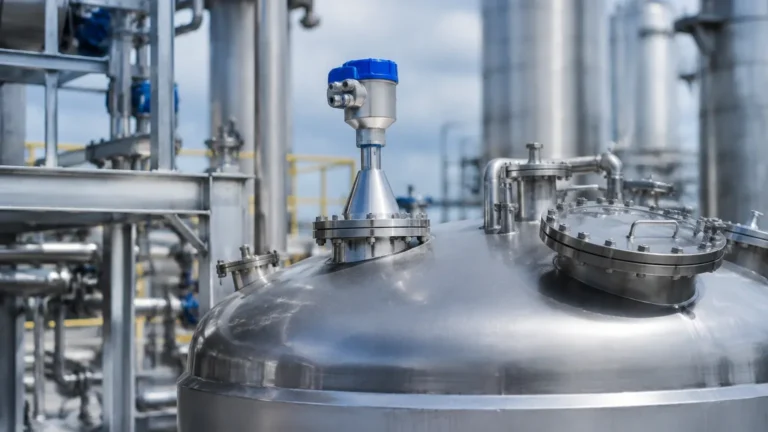
Non Contact Radar Level Transmitter Emerson
Non-Contact Radar Level Transmitters: An Engineering Guide to Selection and Application
In the landscape of industrial automation, accurate level measurement is a cornerstone of process safety and inventory management. Non-contact radar technology has emerged as the preferred solution for challenging environments where mechanical or contact-based sensors fail. Whether evaluating a high-end non contact radar level transmitter emerson (such as the Rosemount 5408 series) or selecting a cost-effective industrial alternative for water treatment, engineers must understand the underlying physics and installation constraints to ensure long-term reliability.
Modern Radar Level Meters utilize high-frequency electromagnetic waves to detect the surface of liquids, solids, and slurries. Because these waves travel at the speed of light and are largely unaffected by air temperature, pressure, or vapor composition, they offer a level of precision that ultrasonic or hydrostatic sensors often cannot match.
Measurement Principles: How Radar Level Meters Work
Non-contact radar transmitters operate on the principle of "Time of Flight" (ToF). The device emits a signal from the antenna, which travels through the tank headspace, reflects off the product surface, and returns to the sensor. The distance is calculated using the formula:
$$D = \frac{c \times t}{2}$$
Where:
- D is the distance to the material surface.
- c is the speed of light ($3 \times 10^8$ m/s).
- t is the measured transit time.
There are two primary modulation techniques used in the industry today:
1. Pulse Radar
Pulse radar sends short bursts of microwave energy and measures the time it takes for the pulse to return. This technology is known for its low power consumption, making it suitable for battery-powered or loop-powered applications in remote areas. However, it generally offers lower resolution compared to continuous wave methods.
2. FMCW (Frequency Modulated Continuous Wave)
FMCW radar, commonly found in high-performance units like the non contact radar level transmitter emerson and Welk’s advanced series, emits a continuous signal with a constantly changing frequency. The distance is determined by the frequency difference between the transmitted and received signals. FMCW provides superior accuracy (often up to ±1 mm), better signal-to-noise ratios, and the ability to distinguish between the actual surface and internal tank obstructions.
Frequency Selection: 26 GHz vs. 80 GHz
The frequency of the radar signal dictates the beam angle and the instrument's ability to handle difficult surfaces.
* 6 GHz to 10 GHz (C-Band): These lower frequencies are less affected by foam, dust, and heavy vapor. They are ideal for applications where the surface is turbulent or covered in a layer of light foam, though they require larger antennas to maintain a narrow beam.
* 26 GHz (K-Band): This is the "workhorse" frequency for most industrial applications. It offers a balance between a narrow beam and resistance to condensation. It is widely used in chemical storage and oil tanks.
* 80 GHz (W-Band): The current state-of-the-art. 80 GHz radar allows for extremely small antennas and a very narrow beam angle (often as small as 3°). This makes it possible to install the meter in tall, narrow nozzles or in tanks with complex internal structures like agitators and heating coils.
Selection Comparison Table
| Feature | 6-10 GHz Radar | 26 GHz Radar | 80 GHz Radar |
| :— | :— | :— | :— |
| Beam Angle | Wide (approx. 20°–30°) | Medium (approx. 8°–12°) | Narrow (approx. 3°–4°) |
| Max Range | Up to 30 m (98 ft) | Up to 70 m (230 ft) | Up to 120 m (394 ft) |
| Accuracy | ±5 mm to ±10 mm | ±2 mm to ±3 mm | ±1 mm |
| Foam Resistance | Excellent | Moderate | Low |
| Nozzle Size | Large (> DN150) | Medium (DN50–DN100) | Small (DN20 to DN40) |
| Typical Use | Turbulent liquids | Chemical process tanks | Tall silos, narrow vessels |
Engineering Considerations for Installation
To achieve the specified accuracy of Radar Level Meters, engineers must adhere to strict installation guidelines. Even a high-performance non contact radar level transmitter emerson will provide erratic readings if the signal path is compromised.
1. Nozzle Geometry
The nozzle height should be kept as short as possible. If the nozzle is too long or has internal burrs, it can create "ringing" or false echoes that mask the true level signal. For 80 GHz units, this is less of a concern, but for 26 GHz units, the antenna should ideally extend slightly below the nozzle opening.
2. Obstruction Clearance
The "beam zone" must be clear of ladders, pipes, and agitators. If an obstruction is unavoidable, many modern transmitters offer "False Echo Suppression" or "Background Subtraction," allowing the software to ignore static reflections. However, it is always better to position the sensor such that the beam has a clear path to the liquid surface.
3. Mounting Position
Radar transmitters should never be mounted in the center of a tank with a domed roof, as this can cause multiple reflections to converge at the sensor, leading to signal interference. Ideally, the sensor should be placed at 1/4 to 1/3 of the tank diameter from the wall, while ensuring it is not too close to the wall to avoid side-lobe interference.
Limitations and Application Risks
While radar is highly versatile, it is not a "one-size-fits-all" solution. Several factors can attenuate the signal:
* Dielectric Constant (DK): The reflectiveness of a material depends on its dielectric constant. Hydrocarbons (like oil or fuel) have low DK values (1.7 to 2.5) and reflect less energy than water (DK ≈ 80). For very low DK materials, a guided wave radar or a high-sensitivity non-contact radar with a large antenna is required.
* Heavy Foam: While some frequencies can penetrate light foam, thick, dense foam (like shaving cream) can absorb the microwave signal entirely, leading to a "loss of echo" error.
* Turbulence and Vortexing: Rapidly moving surfaces can scatter the radar beam. In these cases, using a stilling well or a bypass pipe is recommended to provide a calm surface for measurement.
* Dust and Build-up: In solids applications, heavy dust can attenuate high-frequency signals. Using an air purge connection on the antenna can help keep the lens clean and operational.
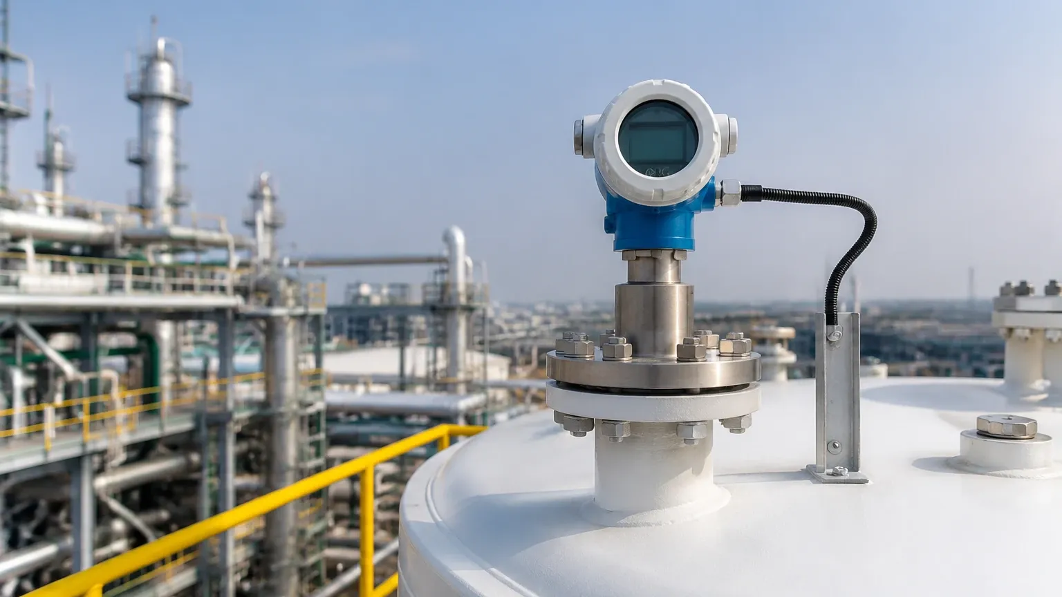
Why Choose Non-Contact Radar Over Guided Wave?
Engineers often debate between non-contact and guided wave radar (GWR). The primary advantage of non-contact radar is that it never touches the process media. This is critical for:
1. Corrosive Media: No need for exotic alloy probes that increase costs.
2. Hygienic Applications: In food and beverage or pharmaceuticals, non-contact sensors prevent contamination and are easier to clean (CIP/SIP).
3. Mechanical Safety: There is no risk of a probe breaking off and damaging downstream equipment like pumps or turbines.
Frequently Asked Questions (FAQ)
Q: How does temperature affect radar level measurement?
A: Unlike ultrasonic sensors, which depend on the speed of sound (which changes with air density and temperature), radar waves are electromagnetic. They are virtually unaffected by temperature fluctuations, making them suitable for extreme environments from -40°C to +250°C (-40°F to +482°F) and beyond with specialized cooling fins.
Q: Can I use a radar level meter in a vacuum?
A: Yes. Since electromagnetic waves do not require a medium to travel, non-contact radar works perfectly in a vacuum. This is a significant advantage over ultrasonic technology, which cannot function without air or gas.
Q: What maintenance is required for non-contact radar transmitters?
A: Because there are no moving parts and no contact with the media, maintenance is minimal. Most issues arise from heavy condensation or material build-up on the antenna lens. Periodic visual inspections and cleaning of the lens (if an air purge is not used) are usually sufficient.
Q: How do I handle a low dielectric constant liquid?
A: If the liquid has a DK below 1.5, you should consider a larger antenna size to increase signal gain or utilize a stilling well to concentrate the signal. Many high-end non contact radar level transmitter emerson models and Welk high-sensitivity units are specifically designed with algorithms to track weak echoes in low-DK applications.
Conclusion
Selecting the right non-contact radar level transmitter requires a thorough analysis of the process media, vessel geometry, and environmental conditions. While the non contact radar level transmitter emerson sets a high bar for performance in critical process industries, understanding the fundamental principles of frequency and beam angle allows engineers to select the most cost-effective and reliable Radar Level Meters for their specific application. By prioritizing proper installation and acknowledging the limitations of dielectric properties and foam, industrial facilities can achieve precise, maintenance-free level monitoring for years to come.
Download Non Contact Radar Level Transmitter Emerson as a PDF