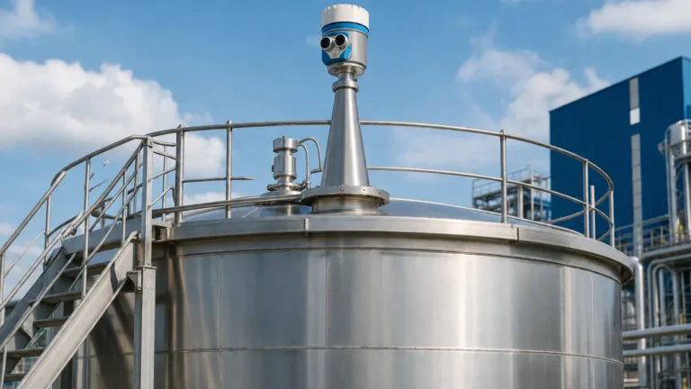
Vega Radar Level Transmitter
Vega Radar Level Transmitter: An Engineering Guide to Selection and Application
In the landscape of industrial process control, accurate level measurement is a fundamental requirement for safety, efficiency, and inventory management. Among the various technologies available, non-contact radar has emerged as the gold standard for challenging environments. The vega radar level transmitter series represents a significant benchmark in this field, particularly with the transition from traditional pulsed radar to high-frequency Frequency Modulated Continuous Wave (FMCW) technology.
This guide provides a technical overview of how Radar Level Meters function, the specific advantages offered by high-end transmitters like those from Vega, and the critical engineering parameters that international buyers must confirm before procurement.
1. Measurement Principles: From Pulse to FMCW
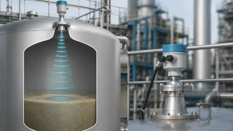
To select the correct instrument, it is essential to understand the underlying physics of radar level measurement. Radar sensors emit electromagnetic waves—typically in the microwave spectrum—which travel at the speed of light. When these waves encounter a medium with a different dielectric constant than the surrounding air or gas, a portion of the energy is reflected back to the sensor.
Time-of-Flight (ToF) Pulse Radar
Traditional radar transmitters used the Time-of-Flight principle. The device emits a short microwave pulse and measures the time interval until the echo is received. While effective, this method requires extremely high-speed electronics to resolve small distances accurately, as light travels approximately 300 mm (11.8 inches) in one nanosecond.
Frequency Modulated Continuous Wave (FMCW)
Modern high-performance units, including many in the vega radar level transmitter portfolio, utilize FMCW technology. Instead of a single pulse, the transmitter emits a continuous signal with a constantly changing frequency (a frequency sweep). The reflected signal is compared to the emitted signal at that exact moment. The frequency difference between the two is directly proportional to the distance. FMCW offers significantly higher signal-to-noise ratios and better resolution, making it ideal for measuring liquids with low reflectivity or in vessels with complex internal geometries.
2. The Impact of Frequency: 26 GHz vs. 80 GHz
One of the most critical decisions in specifying a radar level meter is the operating frequency. This determines the beam angle and the sensor's ability to handle foam, dust, or condensation.
* 26 GHz Radar: Often considered the "all-rounder." It has a wider beam angle, which can be advantageous in applications where the surface is extremely turbulent, as the wider footprint is more likely to capture a return signal. However, the wider beam is more prone to interference from vessel internals like ladders or agitators.
* 80 GHz Radar: This represents the current state-of-the-art for the vega radar level transmitter. The higher frequency allows for a much narrower beam angle (as low as 3 degrees). A narrow beam can be directed precisely between internal obstructions and is less affected by buildup on the vessel walls. Furthermore, 80 GHz sensors can often measure through plastic tank tops or view through narrow nozzles without signal degradation.
3. Engineering Selection Criteria
When evaluating Radar Level Meters for a specific industrial process, engineers must evaluate the following four pillars of application compatibility.
Dielectric Constant (εr)
The dielectric constant of the medium is the most important factor in signal reflection. Materials with high εr (like water, εr ≈ 80) reflect signals strongly. Hydrocarbons and powders often have low εr (1.4 to 2.5), requiring high-sensitivity FMCW transmitters to ensure a reliable echo. If the εr is below 1.4, guided wave radar (GWR) may be a more appropriate choice than non-contact radar.
Process Temperature and Pressure
Standard sensors typically handle up to 80°C (176°F), but industrial processes often exceed this. High-temperature versions of the vega radar level transmitter utilize ceramic seals and specialized cooling fins to withstand temperatures up to 450°C (842°F) and pressures exceeding 160 bar (2320 psi).
Vessel Geometry and Internals
The presence of agitators, heating coils, or baffles creates "false echoes." While modern software can "map out" these reflections, choosing a transmitter with a narrow beam angle (80 GHz) significantly reduces the engineering effort required to commission the device in crowded tanks.
Selection Table for Common Applications
| Application Type | Recommended Frequency | Antenna Material | Key Consideration |
| :— | :— | :— | :— |
| Corrosive Chemicals | 80 GHz | PTFE / PVDF | Chemical compatibility of the wetted parts is paramount. |
| Large Grain Silos | 80 GHz | Plastic Horn / Lens | High frequency penetrates dust better and focuses on the cone. |
| Water/Wastewater | 26 GHz or 80 GHz | Stainless Steel / PP | Focus on IP68 ratings for flooding and condensation resistance. |
| High-Pressure Steam | 26 GHz | Ceramic Seal | Steam can change the speed of the radar wave; compensation may be needed. |
| Small Process Tanks | 80 GHz | Threaded / Small Flange | Narrow beam avoids wall interference in tight spaces. |
4. Installation Guidelines and Constraints
Even the most advanced vega radar level transmitter will fail if installed incorrectly. Engineers should adhere to the following checklist during the design phase:
1. Nozzle Height and Diameter: The antenna should ideally extend slightly below the bottom of the mounting nozzle to prevent "ringing" or internal reflections within the nozzle itself. If using an 80 GHz sensor, the nozzle can be longer and narrower than with 26 GHz units.
2. Distance from Wall: Never mount the transmitter in the center of a tank (which can cause multiple reflections) or too close to the wall. A general rule is to maintain a distance of at least 1/6th of the tank diameter from the wall.
3. Obstruction Clearance: Ensure the radar beam's "footprint" at the bottom of the tank does not intersect with agitator blades or inflow streams. If an inflow stream crosses the beam, it will cause erratic readings.
4. Polarization: Radar waves are polarized. Rotating the sensor during installation can sometimes help minimize reflections from specific internal structures.

5. Limitations and Application Risks
While highly versatile, Radar Level Meters are not universal solutions. Certain conditions can attenuate or block the signal:
* Heavy Foam: Dense, conductive foam can absorb the radar signal entirely, leaving the sensor with no return echo. In these cases, a mechanical or hydrostatic solution may be required.
* Extremely Low Dielectric Media: As mentioned, materials with εr < 1.4 provide very weak reflections. If the surface is also turbulent, the signal may be lost.
* Vacuum Conditions: While radar works in a vacuum (unlike ultrasonic sensors), the mechanical seals of the transmitter must be rated for vacuum service to prevent damage to the electronics.
6. International Buyer’s Technical Checklist
For procurement managers and engineers sourcing a vega radar level transmitter or equivalent high-performance instrumentation, confirming the following technical details is mandatory to avoid costly returns or site failures:
* Medium Properties: What is the exact Dielectric Constant? Is the medium prone to coating or buildup?
* Process Connection: Does the site require Flanged (ANSI/DIN), Threaded (NPT/G), or Hygienic (Tri-Clamp) connections?
* Output Protocol: Is the control system looking for 4-20mA HART, Profibus PA, Foundation Fieldbus, or Modbus RTU?
* Hazardous Area Ratings: Does the installation site require ATEX, IECEx, or FM certifications for explosive atmospheres (Ex d or Ex i)?
* Housing Material: For offshore or corrosive coastal environments, stainless steel housings are preferred over plastic or aluminum.
7. Frequently Asked Questions (FAQ)
Q: Can a radar level transmitter measure through a glass window?
A: Yes. Radar signals can penetrate non-conductive materials like glass, plastic, and ceramics. This allows for measurement in highly toxic or pressurized environments where the sensor is physically isolated from the process.
Q: How does condensation affect the measurement?
A: While 80 GHz radar is better at ignoring small droplets, heavy condensation on the antenna can attenuate the signal. Many vega radar level transmitter models feature a convex lens antenna design that allows droplets to run off, maintaining signal integrity.
Q: Is calibration required on-site?
A: Radar transmitters are typically factory-calibrated. On-site commissioning involves "zeroing" the device (setting the 4mA and 20mA points relative to the tank height) and performing a false-signal suppression scan to map out internal obstructions.
Q: What is the lifespan of a non-contact radar sensor?
A: Because there are no moving parts and the sensor does not touch the medium (in most applications), these units can last 10-15 years or more, provided the electronics are protected from extreme ambient temperatures and power surges.
Conclusion
Selecting a vega radar level transmitter involves more than just picking a part number; it requires a deep understanding of the process environment and the physics of electromagnetic reflection. By prioritizing high-frequency 80 GHz technology for complex vessels and ensuring all process boundary conditions—such as dielectric constants and pressure ratings—are met, facilities can achieve maintenance-free, high-precision level monitoring. For those exploring the broader market of Radar Level Meters, adhering to these engineering principles ensures that the chosen solution will provide reliable data for the duration of the plant's lifecycle.