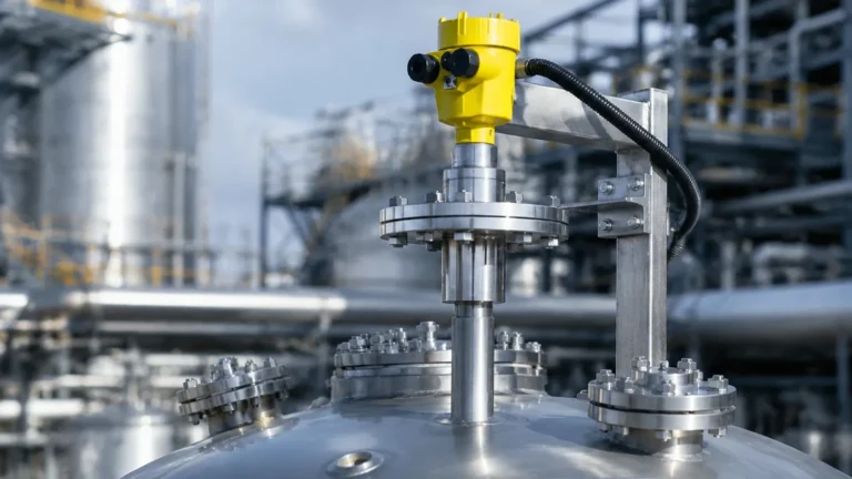
Radar Level Sensor
Radar Level Sensor
In modern industrial process automation, the ability to accurately measure the level of liquids, slurries, and solids is fundamental to operational efficiency, safety, and inventory management. Among the various technologies available, the radar level sensor has emerged as a premier solution due to its non-contact nature and its ability to perform under extreme process conditions.
As a professional manufacturer of industrial instrumentation, Welk provides high-performance Radar Level Meters designed to meet the rigorous demands of the chemical, oil and gas, and water treatment sectors. This guide provides a technical overview of radar technology, selection criteria, and installation best practices for engineering professionals.
Understanding Radar Level Measurement Principles
Radar level measurement is based on the propagation of electromagnetic waves. Unlike ultrasonic sensors, which rely on sound waves and are affected by air temperature and vacuum conditions, radar waves travel at the speed of light and are largely unaffected by the atmosphere in the tank.
The Time of Flight (ToF) Principle
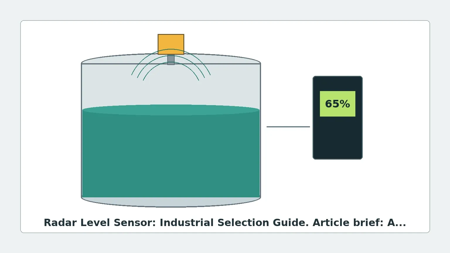
The sensor emits a high-frequency microwave signal toward the product surface. When the signal hits the medium, a portion of the energy is reflected back to the sensor. The instrument measures the time elapsed between emission and reception. Since the speed of light ($c$) is constant, the distance ($D$) to the product surface is calculated as:
$$D = \frac{c \times t}{2}$$
Where $t$ is the measured transit time. The device then subtracts this distance from the total tank height to determine the level.
Pulse Radar vs. FMCW
There are two primary methods used in a modern radar level sensor to process these signals:
1. Pulse Radar: The sensor emits short microwave pulses and measures the time delay of the return echo. This method is energy-efficient and suitable for many standard applications.
2. Frequency Modulated Continuous Wave (FMCW): The sensor emits a continuous signal with a constantly changing frequency. The difference between the frequency being emitted and the frequency being received at any given moment is proportional to the distance. FMCW provides significantly higher accuracy and a better signal-to-noise ratio, making it the standard for high-precision industrial requirements.
Comparing Radar Technologies: Frequency and Beam Angle
The frequency of the radar signal—measured in Gigahertz (GHz)—determines the beam angle and the sensor's ability to handle obstacles or surface turbulence.
* 6 GHz (C-Band): These sensors have a wider beam angle and are less affected by foam or heavy turbulence. However, they require larger antennas and are more prone to interference from internal tank structures like agitators.
* 26 GHz (K-Band): A versatile middle ground, offering a narrower beam than C-band. It is widely used in medium-sized tanks for both liquids and solids.
* 80 GHz (W-Band): The current state-of-the-art for non-contact measurement. The high frequency allows for a very narrow beam angle (often as small as 3°). This precision allows the sensor to avoid internal obstructions and measure accurately in tall, narrow silos or tanks with complex internal geometries.
Non-Contact Radar vs. Guided Wave Radar (GWR)
When selecting a radar level sensor, engineers must choose between non-contact and contact-based (Guided Wave) designs.
| Feature | Non-Contact Radar | Guided Wave Radar (GWR) |
| :— | :— | :— |
| Measurement Method | Microwaves travel through air | Microwaves travel along a probe/cable |
| Installation | Top-mounted, no contact with medium | Probe extends to the bottom of the tank |
| Dielectric Constant | Requires $\epsilon_r$ > 1.4 (typically) | Can measure $\epsilon_r$ as low as 1.2 |
| Maintenance | Extremely low (no moving parts) | Low, but probe may require cleaning |
| Best For | Corrosive liquids, large silos, hygienic | Low dielectric fluids, interface measurement |
Guided Wave Radar is particularly effective for measuring the interface between two liquids (e.g., oil and water) because the signal can penetrate the upper layer and reflect off the lower, more conductive layer.
Critical Selection Criteria for Industrial Applications
To ensure the reliability of a radar level sensor, several process-specific factors must be evaluated during the procurement phase.
1. Dielectric Constant ($\epsilon_r$)
The dielectric constant of the material being measured determines how much energy is reflected back to the sensor. High-dielectric materials like water ($\epsilon_r \approx 80$) reflect signals very strongly. Low-dielectric materials like hydrocarbons or dry powders ($\epsilon_r$ 1.5 to 2.5) reflect very little energy. For low-dielectric materials, an 80 GHz FMCW radar or a Guided Wave Radar is often necessary to capture a usable echo.
2. Process Temperature and Pressure
Standard sensors are often rated up to 80°C (176°F) and 3 bar (43.5 psi). However, industrial applications in oil refining or chemical synthesis may require specialized housings and seals (such as Kalrez or PTFE) to withstand temperatures exceeding 250°C (482°F) and pressures up to 40 bar (580 psi) or higher.
3. Tank Geometry and Obstructions
Internal structures like heating coils, ladders, and agitators can create "false echoes." A radar level sensor with a narrow beam angle (high frequency) is easier to install in such environments. Modern software also allows for "false echo suppression," where the sensor is taught to ignore static reflections from fixed internal structures.
Installation Best Practices and Constraints
Proper installation is the most critical factor in the long-term performance of Radar Level Meters. Engineers should adhere to the following guidelines:
* Nozzle Position: The sensor should not be mounted in the center of a tank (to avoid multiple reflections from the tank walls) nor too close to the wall (to avoid signal attenuation). A common rule of thumb is to place the sensor at 1/4 to 1/6 of the tank diameter from the wall.
* Nozzle Height and Diameter: The antenna should ideally extend slightly below the bottom of the mounting nozzle to prevent the nozzle itself from interfering with the signal. If the nozzle is very long, a high-frequency (80 GHz) sensor is required to maintain a narrow beam.
* Avoid the Inflow: Never install the sensor directly above the point where the tank is filled. The falling product will interfere with the radar signal and cause erratic readings.
* Dead Zone (Blocking Distance): Every radar sensor has a minimum distance (typically 50mm to 200mm) from the antenna where it cannot measure accurately. Ensure the maximum fill level of the tank does not enter this zone.
Limitations and Mitigation Strategies
While highly versatile, radar technology faces specific challenges in certain industrial environments:
1. Heavy Foam: Dense, thick foam can absorb the radar signal entirely. In such cases, a 6 GHz sensor (which penetrates foam better) or a Guided Wave Radar is preferred.
2. Dust and Condensation: While radar penetrates dust better than ultrasonic sensors, extreme dust in grain silos can attenuate the signal. High-power 80 GHz sensors with self-cleaning air purge connections are the standard solution for these environments.
3. Vapor and Gas Layers: Certain chemicals create heavy vapor layers that can change the speed of the microwave signal. While this effect is much smaller than with ultrasonic technology, it may require calibration for high-precision custody transfer applications.
Procurement Checklist for International Buyers
When sourcing a radar level sensor for international projects, ensure the following technical specifications are confirmed with the manufacturer:
* Output Protocol: Does the facility require 4-20mA HART, Modbus RTU, Profibus, or Foundation Fieldbus?
* Hazardous Area Certifications: Ensure the device carries necessary certifications such as ATEX, IECEx, or UL/CSA for explosive atmospheres.
* Wetted Materials: Confirm that the antenna or probe material (e.g., 316L Stainless Steel, PTFE, Hastelloy) is chemically compatible with the process medium.
* Process Connection: Specify the exact flange standard (ANSI, DIN, JIS) or thread type (NPT, G) to avoid installation delays.
Frequently Asked Questions (FAQ)
Q: Can a radar level sensor measure through a plastic tank wall?
A: Yes. Because plastic is non-conductive and has a low dielectric constant, radar waves can pass through the top of a plastic or fiberglass tank, allowing for non-invasive measurement from the outside.
Q: How does agitation affect the measurement?
A: Surface turbulence caused by an agitator can scatter the radar signal. Using a sensor with a high update rate and advanced signal processing (averaging) can mitigate this. For extreme turbulence, a stilling well or Guided Wave Radar is recommended.
Q: Is 80 GHz always better than 26 GHz?
A: Not necessarily. While 80 GHz offers better focus and accuracy, 26 GHz or 6 GHz sensors are often more robust in applications with heavy steam, condensation, or foam, as the longer wavelengths are less likely to be scattered by small droplets.
Conclusion
Selecting the right radar level sensor requires a balance of understanding the physical properties of the medium and the mechanical constraints of the installation site. By choosing the appropriate frequency, technology (non-contact vs. GWR), and material specifications, industrial operators can achieve reliable, maintenance-free level monitoring even in the most challenging environments.
For technical support in selecting the optimal configuration for your specific application, Welk offers a comprehensive range of Radar Level Meters backed by expert engineering assistance and global distribution capabilities.