Radar Level Transmitter Hsn Code
Understanding Radar Level Transmitter HSN Code and Engineering Selection Criteria
In the landscape of industrial automation and process control, the accurate measurement of liquid and solid levels is fundamental to operational efficiency and safety. Among the various technologies available, Radar Level Meters have emerged as a gold standard due to their non-contact nature and reliability in harsh environments. For procurement officers, engineers, and international traders, understanding the technical specifications is only half the battle; navigating the regulatory and logistical framework, specifically the radar level transmitter hsn code, is essential for seamless global supply chain management.
This guide provides a comprehensive technical overview of radar level measurement technology, selection parameters, and the administrative classifications required for international trade.
1. Measurement Principles of Radar Level Technology
Radar level transmitters operate on the principle of microwave propagation. Unlike ultrasonic sensors, which rely on sound waves and are susceptible to air temperature and pressure changes, radar waves travel at the speed of light and are largely unaffected by the vapor space atmosphere. There are two primary methods used in industrial radar measurement: Pulse Radar and Frequency Modulated Continuous Wave (FMCW).
Pulse Radar (Time of Flight)
Pulse radar instruments emit a short microwave pulse toward the product surface. The instrument measures the time it takes for the pulse to travel to the surface and reflect back to the sensor. Since the speed of light is constant, the distance is calculated using the formula:
\[ Distance = \frac{c \times t}{2} \]
Where *c* is the speed of light and *t* is the measured transit time. This method is energy-efficient and suitable for many standard liquid applications.
Frequency Modulated Continuous Wave (FMCW)
FMCW radar transmits a continuous signal with a constantly changing frequency (a frequency sweep). The reflected signal is received and compared to the signal being transmitted at that moment. The frequency difference between the transmitted and received signals is directly proportional to the distance. FMCW is generally more accurate than pulse radar and is preferred for high-precision applications or environments with significant surface agitation.
2. The Radar Level Transmitter HSN Code and International Trade
When importing or exporting industrial instrumentation, the Harmonized System of Nomenclature (HSN) code is vital for determining customs duties, taxes, and regulatory compliance. The radar level transmitter hsn code typically falls under Chapter 90 of the HSN system, which covers "Optical, photographic, cinematographic, measuring, checking, precision, medical or surgical instruments."
Primary Classification
For most international jurisdictions, the base 6-digit HS code is 9026.10. This category is defined as:
* 9026: Instruments and apparatus for measuring or checking the flow, level, pressure or other variables of liquids or gases.
* 9026.10: For measuring or checking the level of liquids.
Specific 8-Digit HSN Codes
Depending on the country (such as India or members of the EU), the code may be extended to 8 digits for more specificity:
* 9026 10 10: Often used for level gauges.
* 9026 10 90: Often used for "Other" electronic level measuring instruments, including advanced Radar Level Meters.
It is critical for B2B buyers to verify the specific 8-digit code with their local customs authority, as misclassification can lead to shipment delays or incorrect tariff applications. For example, if a radar transmitter is integrated into a larger control system, it might occasionally be classified under the system's primary code, though standing alone, 9026.10 remains the standard.
3. Engineering Selection Criteria
Selecting the correct radar level transmitter requires a deep dive into the process conditions. The following table summarizes the key factors to consider when evaluating different radar technologies.
Selection Comparison Table
| Feature | 6 GHz Radar | 26 GHz Radar | 80 GHz Radar |
| :— | :— | :— | :— |
| Beam Angle | Wide (approx. 20-30°) | Medium (approx. 8-12°) | Narrow (approx. 3-4°) |
| Antenna Size | Large | Medium | Small (Compact) |
| Dust/Vapor Resistance | Excellent | Good | Moderate (requires purging) |
| Accuracy | ±5 mm to ±10 mm | ±2 mm to ±5 mm | ±1 mm |
| Typical Application | Turbulent liquids, heavy steam | Standard tanks, chemical storage | Narrow vessels, high precision |
Dielectric Constant (εr)
The dielectric constant of the medium is the most critical factor in radar measurement. It determines how much energy is reflected back to the sensor.
* High εr (>10): Water-based liquids provide strong reflections and are easy to measure.
* Low εr (1.4 to 4): Hydrocarbons, oils, and some solids reflect very little energy. In these cases, high-sensitivity FMCW radar or Guided Wave Radar (GWR) may be required.
4. Installation Considerations and Best Practices
Proper installation is paramount to ensuring the reliability of radar level transmitters. Even the most advanced sensor will fail if placed incorrectly.
Nozzle Geometry and Placement
* Avoid the Center: Never install a radar sensor in the exact center of a domed tank, as this can cause multiple reflections (parabolic effect) that interfere with the signal.
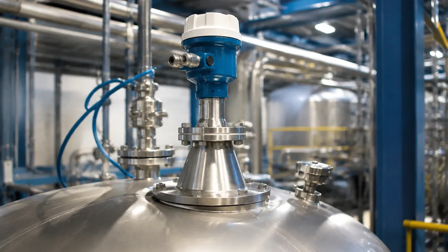
* Nozzle Height: The nozzle should be as short as possible. If the nozzle is too long, the radar beam may reflect off the internal walls of the nozzle before reaching the process medium.
* Obstructions: Ensure the beam path is clear of internal tank structures such as ladders, agitators, or heating coils. If obstructions are unavoidable, most modern Radar Level Meters feature "false echo suppression" software to map out and ignore these static reflections.
Beam Angle Calculation
The beam angle is defined as the area where the energy density is half of its maximum. To calculate the diameter of the footprint at the bottom of the tank:
\[ D = 2 \times L \times \tan(\frac{\alpha}{2}) \]
Where *D* is the footprint diameter, *L* is the distance (tank height), and *α* is the beam angle. This calculation ensures the beam does not hit the tank wall before reaching the minimum product level.
5. Limitations and Application Risks
While radar is highly versatile, engineers must be aware of its limitations:
1. Heavy Foam: Dense, thick foam can absorb or scatter the radar signal, leading to signal loss. In such cases, a magnetic level gauge or a hydrostatic transmitter might be more appropriate.
2. Agitated Surfaces: Extreme turbulence can scatter the signal. This is often mitigated by using a stilling well or a bypass chamber to provide a calm surface for measurement.
3. Vacuum Conditions: While radar works in a vacuum, the mechanical seals and flange ratings must be specifically designed for such environments.
4. Condensation: Heavy condensation on the antenna can attenuate the signal. High-frequency (80 GHz) units with PTFE lens antennas are often designed to shed droplets more effectively than traditional horn antennas.
6. Frequently Asked Questions (FAQ)
Q: Does the radar level transmitter hsn code change if the device is wireless?
A: Generally, the HSN code remains 9026.10 as the primary function is level measurement. However, some regions may require additional classification under Chapter 85 if the radio transmission component is considered the primary feature, though this is rare for industrial sensors.
Q: Can radar measure the level of solids like cement or grain?
A: Yes. High-frequency 26 GHz or 80 GHz radar is excellent for solids. Because solid surfaces are often angled (angle of repose), a narrow beam and high sensitivity are required to capture the reflected signal.
Q: What is the difference between Non-Contact Radar and Guided Wave Radar (GWR)?
A: Non-contact radar sends waves through the air. GWR (HSN code 9026.10) uses a physical probe (cable or rod) to guide the microwave to the surface. GWR is better for low dielectric liquids and applications with heavy foam or turbulence.
Q: Is calibration required for radar level meters?
A: Most radar transmitters are factory-calibrated. However, "field mapping" or "wet calibration" is recommended during commissioning to account for the specific geometry of the tank and to suppress false echoes from internal obstructions.
7. Maintenance and Troubleshooting
Radar level transmitters are low-maintenance because they have no moving parts. However, periodic checks are recommended:
* Antenna Cleaning: In sticky or crystallizing media, check the antenna for buildup. Many horn antennas can be equipped with a purging port to clean the sensor with compressed air or water without removing it from the process.
* Signal Strength Monitoring: Modern digital transmitters provide a "Signal-to-Noise Ratio" (SNR). A declining SNR over time may indicate antenna fouling or a change in the dielectric properties of the medium.
* Cable Glands and Seals: Ensure that moisture has not entered the electronics housing through improperly sealed cable entries, especially in outdoor or wash-down environments.
By carefully considering the technical requirements of the application and ensuring the correct administrative classification via the radar level transmitter hsn code, industrial professionals can ensure both technical success and regulatory compliance in their level measurement projects. For more detailed specifications on frequency options and antenna types, engineers should review the available Radar Level Meters to match the instrument to their specific process environment.