Radar Level Transmitter Tank
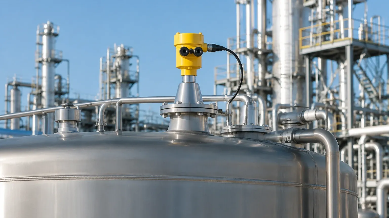
Radar Level Transmitter Tank: A Comprehensive Engineering Guide to Selection and Application
In the landscape of industrial process automation, the ability to accurately monitor the contents of a vessel is fundamental to safety, efficiency, and inventory management. Among the various technologies available, the use of a radar level transmitter tank configuration has become the industry standard for challenging environments. Utilizing electromagnetic waves to determine distance, these instruments offer a non-contact solution that remains largely unaffected by changes in temperature, pressure, or the presence of dust and vapors.
Selecting the right Radar Level Meters requires a deep understanding of both the measurement physics and the specific geometry of the tank in question. This guide explores the engineering principles, selection criteria, and installation requirements for implementing radar technology in industrial tank applications.
1. Measurement Principles of Radar Level Technology
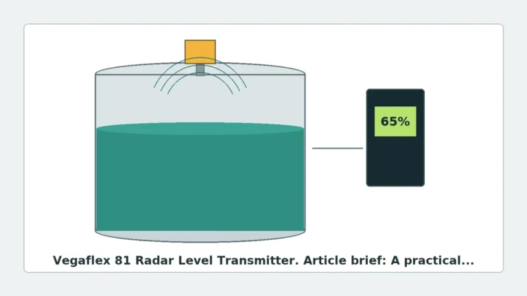
Radar level transmitters operate on the principle of Time of Flight (ToF). The device emits a high-frequency microwave signal toward the product surface, which reflects a portion of that energy back to the sensor. By measuring the time interval between emission and reception, the transmitter calculates the distance to the surface and, consequently, the level within the tank.
In industrial applications, two primary methods of signal processing are used:
Pulse Radar
Pulse radar emits short microwave bursts and measures the time it takes for the pulse to travel to the surface and back. This method is energy-efficient and suitable for many standard storage applications. However, it may struggle with very low dielectric materials or highly turbulent surfaces where signal clarity is compromised.
FMCW (Frequency Modulated Continuous Wave)
FMCW radar transmits a continuous signal with a constantly changing frequency. The difference in frequency between the transmitted and received signal is directly proportional to the distance. This method provides superior accuracy and a higher signal-to-noise ratio, making it the preferred choice for complex radar level transmitter tank setups involving internal obstructions, agitators, or heavy steam.
2. Understanding Frequency: 26GHz vs. 80GHz
The frequency of the radar signal significantly impacts its performance within a tank. For decades, 6GHz and 26GHz were the standards, but recent advancements have made 80GHz technology the dominant choice for new installations.
* 26GHz Radar: Features a wider beam angle. It is effective for larger tanks where the signal needs to cover a broader area, but it is more susceptible to interference from tank walls and internal structures like ladders or heating coils.
* 80GHz Radar: Offers a much narrower beam angle (often as small as 3 degrees). This precision allows the signal to bypass internal obstructions and makes it ideal for tall, narrow tanks or vessels with complex internals. The higher frequency also results in better reflection from low-dielectric media and improved performance in the presence of foam or condensation.
3. Selecting the Right Radar Level Transmitter for Your Tank
When specifying a radar level transmitter tank solution, several technical factors must be evaluated to ensure long-term reliability. The choice depends on the media properties, the vessel environment, and the required precision.
Media Properties and Dielectric Constant ($ε_r$)
The dielectric constant of the liquid or solid being measured is the most critical factor in signal reflection. Water has a high $ε_r$ (~80) and reflects radar waves very well. In contrast, hydrocarbons and oils have low $ε_r$ values (1.7 to 2.5), which absorb more energy and return a weaker signal. For materials with very low dielectric constants, Guided Wave Radar (GWR) or high-frequency 80GHz non-contact radar is recommended.
Tank Geometry and Internals
The shape of the tank (cylindrical, spherical, or horizontal) and the presence of internal components (agitators, baffles, or spray balls) dictate the antenna type and mounting position. A narrow-beam radar is essential if the tank contains a central agitator to avoid "false echoes" from the moving blades.
Process Conditions
High temperatures and pressures require specific flange ratings and sealing materials (such as PTFE or PEEK). If the application involves corrosive chemicals, the wetted parts of the radar level transmitter must be constructed from compatible materials like 316L Stainless Steel or Hastelloy.
4. Technical Selection Table
The following table provides a general comparison of radar technologies based on typical tank application requirements:
| Feature | 26GHz Non-Contact Radar | 80GHz Non-Contact Radar | Guided Wave Radar (GWR) |
| :— | :— | :— | :— |
| Best Use Case | Large storage tanks, simple liquids | Small vessels, agitators, solids | Low dielectric media, bypass pipes |
| Beam Angle | 8° to 20° (Wide) | 3° to 6° (Narrow) | N/A (Signal follows probe) |
| Accuracy | ±3mm to ±5mm | ±1mm to ±2mm | ±2mm |
| Max Range | Up to 30m | Up to 120m | Up to 75m |
| Obstruction Handling | Fair | Excellent | Excellent |
| Foam Resistance | Moderate | High | High (with specific probes) |
5. Installation Best Practices for Tank Radars
Correct installation is paramount to the performance of a radar level transmitter tank system. Even the most advanced sensor will fail if placed incorrectly. Engineers should adhere to the following guidelines:
Nozzle Design and Placement
* Distance from Wall: The transmitter should typically be installed at 1/6th to 1/4th of the tank diameter away from the side wall. Installing too close to the wall causes interference, while installing in the exact center can lead to multiple reflections (standing waves) in dome-top tanks.
* Nozzle Height: The nozzle should be as short as possible. If the nozzle is too long or narrow, the radar signal may reflect off the internal edges of the nozzle before even entering the tank, creating a "dead zone" at the top of the measurement range.
Avoiding Obstructions
The radar beam is conical. Engineers must ensure that the "signal cone" does not intersect with ladders, pipes, or the inflow stream of the product. If an obstruction is unavoidable, many modern Radar Level Meters feature "false echo suppression" software, allowing the user to map out and ignore static reflections.
Alignment
The antenna must be mounted perpendicular to the product surface. For bulk solids, where the material forms a cone (angle of repose), an adjustable flange or aiming kit may be necessary to maximize the reflected signal strength.
6. Overcoming Process Challenges
Industrial tanks are rarely "clean" environments. Several factors can attenuate or distort the radar signal:
Foam and Turbulence
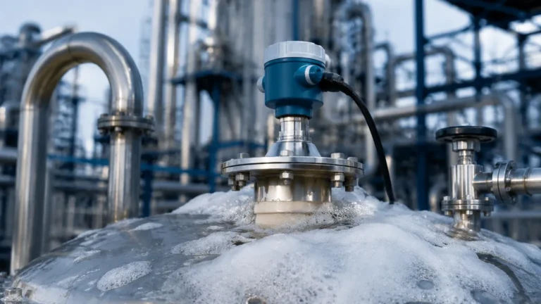
Heavy, dense foam can absorb the radar signal, leading to a loss of echo. In such cases, a lower frequency radar (which penetrates foam better) or a Guided Wave Radar (where the signal is concentrated along a probe) may be more effective. Turbulence on the liquid surface can scatter the signal; using a stilling well or bypass pipe can provide a calm surface for accurate measurement.
Condensation and Buildup
In tanks containing hot liquids, condensation can form on the antenna lens. While 80GHz radars with PTFE lenses are designed to shed droplets, extreme buildup can still cause signal attenuation. Air purging systems or specialized "drip-off" antenna designs are often used in these scenarios to keep the sensor face clear.
Vacuum and High Pressure
Radar waves do not require a medium to travel, making them ideal for vacuum tanks. However, the mechanical seal of the transmitter must be rated for the specific pressure and vacuum levels of the process to prevent leakage or damage to the electronics.
7. Maintenance and Calibration
One of the primary advantages of non-contact radar level transmitter tank systems is the minimal maintenance required. Since there are no moving parts in contact with the media, wear and tear is significantly reduced. However, a periodic maintenance schedule should include:
1. Visual Inspection: Check the antenna for any significant coating or corrosion.
2. Signal Quality Check: Use the device's diagnostic software to monitor the "echo curve." A diminishing signal-to-noise ratio may indicate antenna fouling or a failing component.
3. Verification: Periodically verify the radar reading against a manual dip-tape or a secondary level gauge to ensure calibration has not drifted.
8. Frequently Asked Questions (FAQ)
Q: Can a radar transmitter see through a plastic tank roof?
A: Yes, microwaves can penetrate non-conductive materials like plastic or fiberglass. This allows for "tank-side" measurement where the sensor is mounted outside the vessel, provided the material thickness does not cause excessive attenuation.
Q: Is radar suitable for measuring solids like powders or grains?
A: Absolutely. High-frequency 80GHz radar is particularly effective for solids because it can handle the uneven surfaces and low dielectric properties of bulk materials better than ultrasonic or lower-frequency radar.
Q: What is the "Dead Zone" or "Blocking Distance"?
A: This is the area immediately below the antenna where the device cannot perform a measurement. It is usually defined by the antenna length and the time required for the electronics to switch from transmit to receive mode. It is vital to account for this when determining the maximum fill level of the tank.
Q: Does the color of the liquid affect the radar measurement?
A: No. Unlike optical or laser sensors, radar is entirely unaffected by the color, transparency, or light conditions within the tank.
Conclusion
Implementing a radar level transmitter tank solution requires a balance of theoretical knowledge and practical application engineering. By selecting the appropriate frequency, antenna type, and mounting location, industrial operators can achieve highly accurate and maintenance-free level measurement in even the most demanding environments. Whether dealing with corrosive chemicals, pressurized gases, or bulk solids, Welk provides the technical expertise and robust instrumentation needed to optimize your process levels with confidence.