Radar Level Transmitter Tender
Radar Level Transmitter Tender: A Technical Procurement Guide
In the landscape of industrial process automation, the procurement of instrumentation through a radar level transmitter tender requires a deep understanding of both the physical principles of measurement and the specific environmental constraints of the application. Radar level measurement has become the preferred choice for many industries—including water treatment, chemical processing, and oil and gas—due to its non-contact nature and its ability to operate reliably under extreme pressures and temperatures.
When preparing a tender, engineers must look beyond simple price points. A successful technical specification ensures that the selected Radar Level Meters are compatible with the dielectric properties of the medium, the vessel geometry, and the communication protocols of the plant's control system. This guide outlines the essential technical criteria and selection logic required to draft a robust tender document.
Understanding Radar Level Measurement Principles
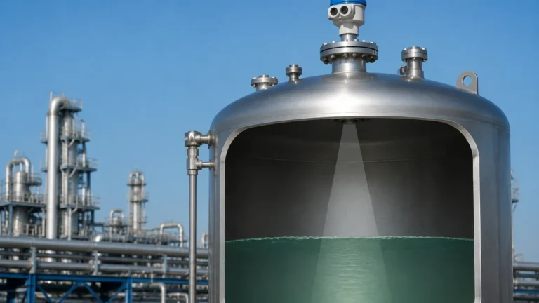
Before specifying equipment in a radar level transmitter tender, it is critical to understand how these devices function. Radar level transmitters operate on the principle of Time of Flight (ToF) using electromagnetic waves. The device emits a high-frequency signal toward the product surface, which is then reflected back to the sensor. The time taken for the signal to travel to the surface and back is directly proportional to the distance.
There are two primary technologies used in modern industrial radar sensors:
1. Pulse Radar
Pulse radar instruments emit a series of short-duration microwave pulses. The electronics measure the time delay between the transmitted pulse and the received echo. While historically common, pulse radar is increasingly being replaced by more sophisticated technologies due to its lower signal-to-noise ratio in complex environments.
2. FMCW (Frequency Modulated Continuous Wave)
FMCW radar transmits a continuous signal with a constantly changing frequency. The difference between the frequency of the transmitted signal and the received signal (the "beat frequency") is used to calculate the distance. FMCW offers significantly higher accuracy and better signal processing capabilities, making it the standard for high-precision industrial applications. Most modern 26GHz and 80GHz transmitters utilize FMCW technology.
Key Factors in a Radar Level Transmitter Tender
A comprehensive tender must define several critical parameters to ensure the equipment provided by manufacturers like Welk meets the operational requirements. Failure to specify these can lead to measurement instability or premature sensor failure.
Frequency Selection
The frequency of the radar signal determines the beam angle and the sensor's ability to handle obstacles and foam.
- 6GHz Radar: Features a wide beam angle and high energy. It is traditionally used in applications with heavy steam or turbulence where a narrow beam might be easily scattered.
- 26GHz Radar: The industrial standard for many years. It offers a balance between beam focus and signal strength, suitable for medium-sized tanks and most liquid chemicals.
- 80GHz Radar: The current state-of-the-art. It provides an extremely narrow beam angle (often as low as 3°), allowing for installation in small nozzles or vessels with internal obstructions like agitators and heating coils.
Dielectric Constant (εr)
The dielectric constant of the material being measured is the most important factor in signal reflection. Materials with high dielectric constants (e.g., water, εr ≈ 80) reflect signals strongly. Hydrocarbons and oils have low dielectric constants (εr < 2.5), which result in much weaker reflections. The tender must specify the minimum dielectric constant the transmitter needs to detect.
Process Conditions
The tender should clearly state the following:
- Operating Temperature: Range from -40°C up to +250°C (or higher for specialized high-temp versions).
- Operating Pressure: From vacuum conditions to high-pressure environments (e.g., 40 bar or 4.0 MPa).
- Chemical Compatibility: Wetted materials such as 316L Stainless Steel, PTFE, or Hastelloy must be specified based on the corrosivity of the medium.
Technical Specification Requirements
To ensure uniformity in the radar level transmitter tender responses, the following technical specifications should be standardized:
| Feature | Specification Detail |
| :— | :— |
| Measurement Range | Specify in meters (e.g., 0–30m, 0–120m for tall silos). |
| Accuracy | Standard industrial accuracy is typically ±2mm or ±3mm. |
| Output Signal | 4-20mA with HART is standard; Modbus RTU, Profibus, or Foundation Fieldbus for digital integration. |
| Power Supply | 2-wire (loop-powered) or 4-wire (separate power) configurations. |
| Housing Material | Aluminum alloy or Stainless Steel for corrosive or offshore environments. |
| Ingress Protection | Minimum IP66/IP67; IP68 for submersible or outdoor washdown areas. |
| Certifications | ATEX/IECEx for hazardous areas; SIL2/SIL3 for safety-instrumented systems. |
Selection Table for Industrial Applications
Choosing the right technology within a tender depends heavily on the specific application. Use the following table as a reference for selection logic:
| Application Type | Recommended Technology | Frequency | Key Benefit |
| :— | :— | :— | :— |
| Storage Tanks (Water/Chemicals) | Non-contact FMCW | 26GHz | Reliable, cost-effective, standard mounting. |
| Small Vessels with Agitators | Non-contact FMCW | 80GHz | Narrow beam avoids internal obstructions. |
| Deep Wells / Tall Silos | High-Power FMCW | 80GHz | Long-range capability with high focus. |
| Extreme Steam/Vapor | Low-Frequency Pulse | 6GHz | Better penetration through heavy vapor clouds. |
| Corrosive Acids | PTFE Flanged Radar | 26GHz/80GHz | Complete chemical isolation of the sensor. |
Installation Constraints and Engineering Considerations
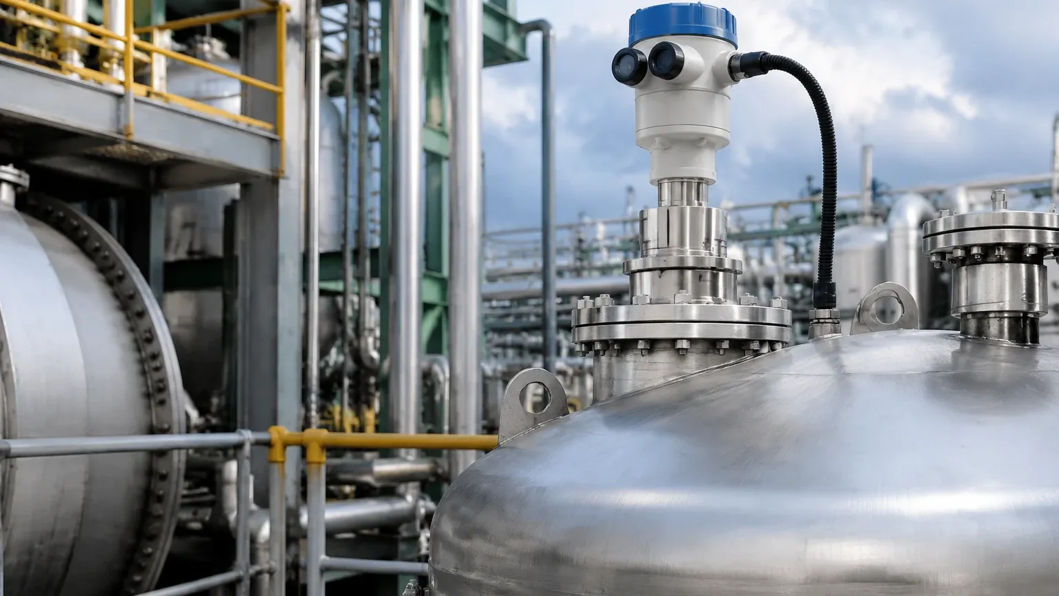
A radar level transmitter tender is not complete without addressing the physical installation environment. Even the most advanced radar will fail if installed incorrectly.
1. Nozzle Dimensions
The height and diameter of the mounting nozzle are critical. If the nozzle is too tall or narrow, the radar signal may reflect off the nozzle walls before reaching the medium, creating a "false echo." 80GHz radars are more forgiving of nozzle geometry due to their narrow beam.
2. Blocking Distance (Dead Zone)
Every radar sensor has a minimum distance it cannot measure, typically 100mm to 300mm from the sensor face. The tender must account for this if the tank is filled to the very top.
3. Obstructions and False Echoes
Internal structures like ladders, pipes, and agitator blades can reflect signals. Modern radar level meters include "False Echo Suppression" software, which allows the user to map out these static reflections so the transmitter ignores them.
4. Beam Path
The radar beam must have a clear path to the liquid surface. It should not be installed too close to the tank wall (to avoid multipath interference) or directly above the filling inlet (to avoid measuring the falling stream).
Limitations and Application Risks
While radar is highly versatile, certain conditions pose risks that must be addressed in the tender evaluation:
* Heavy Foam: Dense, thick foam can absorb or scatter radar signals. If the foam is conductive and thick, the radar may measure the top of the foam rather than the liquid. In such cases, testing or guided wave radar might be required.
* Extremely Low Dielectric Materials: For materials like liquefied gases or certain solvents with εr < 1.4, the reflection may be too weak for standard non-contact radar. High-sensitivity electronics or a stilling well may be necessary.
* Vacuum Conditions: While radar works in a vacuum, the sealing of the process connection (e.g., glass-to-metal seals) must be specified to prevent leakage.
Frequently Asked Questions (FAQ)
Q: Why choose 80GHz over 26GHz in a tender?
A: 80GHz provides a much narrower beam (3° vs 10°). This allows for smaller process connections (as small as 3/4") and makes it easier to avoid internal tank obstructions, leading to a more reliable measurement in complex vessels.
Q: How does the dielectric constant affect the tender specification?
A: If you are measuring a low-dielectric fluid like diesel or oil, you must specify a high-sensitivity radar. If the dielectric constant is unknown, it is safer to request a device with a wider dynamic range.
Q: Is 2-wire or 4-wire better for industrial radar?
A: 2-wire (loop-powered) is preferred for most applications because it simplifies wiring and reduces installation costs. 4-wire is usually reserved for high-power applications or where specialized communication and heating elements are required.
Q: Can radar measure through a plastic tank roof?
A: Yes, non-contact radar can measure through plastic or fiberglass tank tops without a process opening, provided the material is not conductive and does not contain metal reinforcement.
Conclusion
Conducting a radar level transmitter tender requires a balance between technical precision and practical application knowledge. By clearly defining the measurement principle required (FMCW), the necessary frequency (26GHz vs 80GHz), and the specific process conditions (temperature, pressure, and dielectric constant), procurement teams can ensure they receive bids that are technically compliant and fit for purpose.
For engineers and buyers, the goal is to select a solution that offers long-term stability and minimal maintenance. Utilizing the expertise of a professional manufacturer like Welk ensures that the instruments provided meet the rigorous demands of modern industrial automation, providing accurate data for process control and inventory management.