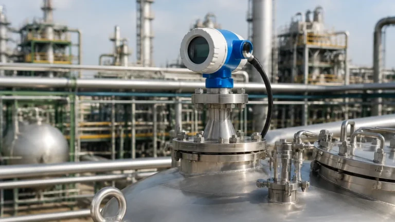
Radar Level Transmitter Wiring Diagram
Radar Level Transmitter Wiring Diagram: A Technical Engineering Guide
In modern industrial process automation, precise level measurement is critical for inventory management, process safety, and operational efficiency. Among the various technologies available, Radar Level Meters have become the industry standard for non-contact measurement in challenging environments. However, the reliability of these instruments depends not only on the sensor technology but also on correct electrical integration. Understanding a radar level transmitter wiring diagram and the underlying electronics is essential for instrumentation engineers and site technicians.
This guide explores the measurement principles of radar technology, details the various wiring configurations (2-wire vs. 4-wire), and provides practical installation and selection criteria for industrial applications.
1. Measurement Principles of Radar Level Meters
Before diving into the wiring and electrical characteristics, it is important to understand how these devices function. Radar level transmitters typically utilize one of two primary methods to determine the distance to a product surface.
Time of Flight (ToF) / Pulse Radar
Pulse radar transmitters emit high-frequency microwave pulses toward the target material. These pulses travel at the speed of light, reflect off the surface of the medium, and return to the sensor antenna. The device measures the time elapsed between emission and reception.
The distance ($D$) is calculated using the formula:
$D = (c \times t) / 2$
Where $c$ is the speed of light and $t$ is the transit time. Because the speed of light is constant, the accuracy depends on the precision of the internal clock and the ability to distinguish the true echo from background noise.
Frequency Modulated Continuous Wave (FMCW)
FMCW radar does not send discrete pulses. Instead, it emits a continuous signal with a frequency that changes linearly over time (a frequency sweep). When the reflected signal is received, it is compared to the signal being emitted at that exact moment. The difference in frequency ($Δf$) is directly proportional to the distance. FMCW is generally more accurate than pulse radar and is preferred for high-precision applications or materials with low dielectric constants.
2. Understanding the Radar Level Transmitter Wiring Diagram
The electrical interface of a radar transmitter serves two purposes: providing power to the electronics and transmitting the measurement signal to a Control Room, PLC (Programmable Logic Controller), or DCS (Distributed Control System). The most common configurations are 2-wire and 4-wire systems.
2-Wire (Loop-Powered) Configuration
In a 2-wire system, the power supply and the output signal share the same pair of wires. This is the most common configuration for modern industrial radar meters due to reduced cabling costs and simplified installation.
* Signal Type: 4-20mA DC with superimposed HART (Highway Addressable Remote Transducer) digital communication.
* Power Supply: Typically 24V DC (range of 12V to 36V DC).
* Wiring Logic: The transmitter acts as a variable resistor, regulating the current in the loop between 4mA (empty) and 20mA (full).
Typical 2-Wire Wiring Diagram Description:
1. Terminal 1 (+): Connected to the positive terminal of the 24V DC power supply.
2. Terminal 2 (-): Connected to the positive input of the PLC/DCS analog input card.
3. Return Path: The negative terminal of the PLC/DCS input card connects back to the negative terminal of the power supply.
4. Grounding: The internal ground terminal should be connected to the plant’s functional earth to minimize Electromagnetic Interference (EMI).
4-Wire Configuration
4-wire transmitters use separate pairs for power and signal. This is necessary for high-power applications, such as units with integrated heating elements for antenna de-icing or high-performance FMCW units that require more current than a 4-20mA loop can provide.
* Power Supply: Can be 24V DC, 110V AC, or 230V AC.
* Signal Type: Passive or active 4-20mA output, often with separate relays for limit switching.
Typical 4-Wire Wiring Diagram Description:
1. Terminals 1 & 2 (Power): Connected to the external power source (L/N for AC or +/- for DC).
2. Terminals 3 & 4 (Signal): Connected to the PLC/DCS. If the output is "active," the transmitter provides the loop power. If "passive," an external source is required.
3. Communication Protocols and Digital Integration
While the radar level transmitter wiring diagram focuses on physical connections, the data transmitted often goes beyond a simple analog signal.
* HART Protocol: Most 2-wire radar meters support HART. This allows technicians to perform configuration, diagnostics, and calibration using a handheld communicator or a PC-based software (via a HART modem) without interrupting the 4-20mA signal.
* RS485 / Modbus RTU: Common in tank farm applications where multiple sensors are daisy-chained over long distances to a single gateway.
* Foundation Fieldbus / Profibus PA: Used in fully digital plant architectures where the instrument is a node on a high-speed fieldbus network.
4. Selection Criteria for Radar Level Meters
Choosing the right radar meter requires balancing frequency, antenna design, and process conditions. The following table provides a comparison between common industrial radar frequencies.
| Feature | 26 GHz Radar | 80 GHz Radar |
| :— | :— | :— |
| Beam Angle | Wider (approx. 10°–15°) | Narrow (approx. 3°–4°) |
| Accuracy | ±3mm to ±5mm | Up to ±1mm |
| Nozzle Sensitivity | Sensitive to nozzle reflections | High immunity to nozzle interference |
| Dust/Steam Penetration | Excellent | Good, but can be affected by heavy condensation |
| Typical Applications | Large storage tanks, aggressive chemicals | Small vessels, narrow silos, high-precision custody transfer |
Antenna Selection
* Horn Antenna: Standard for most liquid applications.
* Parabolic Antenna: Used for long-range measurements (up to 70m or 100m) and solid materials.
* Lens Antenna (PTFE/PP): Ideal for corrosive environments where the antenna must be sealed from the process vapors.

5. Installation Considerations and Constraints
Even with a perfect radar level transmitter wiring diagram execution, physical installation errors can lead to signal loss or false readings. Follow these engineering guidelines:
1. Avoid the Center: Never mount a radar transmitter in the dead center of a dome-roof tank. This can cause multiple reflections to converge, creating a "false echo" that overrides the actual level signal.
2. Beam Path Clearance: Ensure the radar beam (based on the beam angle) does not intersect with internal tank structures like ladders, heating coils, or agitators. If obstructions are unavoidable, use the "False Echo Suppression" feature in the software to map out these static reflections.
3. Nozzle Height: The antenna should ideally extend slightly beyond the mounting nozzle. If the nozzle is too long, the radar waves will reflect off the nozzle walls, creating a large "dead zone" at the top of the tank.
4. Turbulence and Foam: While radar is superior to ultrasonic sensors in turbulent conditions, heavy foam can absorb the microwave signal. In such cases, a stilling well (bypass pipe) may be required to provide a clear, calm surface for measurement.
6. Application Risks and Limitations
Engineers must be aware of the following factors that can impact the performance of Radar Level Meters:
* Dielectric Constant (εr): Radar depends on the reflectivity of the medium. Materials with low dielectric constants (e.g., hydrocarbons, oils, or plastic pellets) reflect less energy. For materials with εr < 1.9, a high-sensitivity FMCW radar or a guided wave radar (GWR) might be necessary.
* Condensation and Buildup: Conductive buildup on the antenna can attenuate the signal. For applications involving heavy vapor or crystallization, choose an antenna with a PTFE cover or an integrated air purge connection to keep the lens clean.
* Pressure and Temperature: While radar is generally unaffected by gas space changes, the mechanical seal of the transmitter must be rated for the process pressure and temperature. High-temperature versions often include a cooling neck to protect the electronics.
7. Frequently Asked Questions (FAQs)
Q: Can I use a standard unshielded cable for radar transmitter wiring?
A: It is highly recommended to use shielded, twisted-pair cables. The shield protects the 4-20mA signal from electromagnetic noise generated by nearby motors or VFDs (Variable Frequency Drives). The shield should be grounded at one end only (usually the control room side) to prevent ground loops.
Q: What is the difference between active and passive 4-20mA outputs in a 4-wire diagram?
A: An active output means the transmitter provides the 24V DC power for the current loop. A passive output means the transmitter acts as a sink, and the receiving device (PLC) or an external power supply must provide the loop voltage.
Q: How do I troubleshoot a "Signal Lost" error?
A: First, check the wiring for loose connections or water ingress in the housing. Second, verify the power supply voltage at the transmitter terminals (it should be >12V DC for most 2-wire units). Third, check for antenna coating or obstructions in the tank. Finally, use a HART communicator to check the echo curve; if the signal is too weak, the gain may need adjustment.
Q: Does the tank material affect the wiring or measurement?
A: The tank material does not affect the wiring, but it does affect the measurement. Metal tanks are excellent at containing radar energy, while plastic or fiberglass tanks may allow the radar signal to pass through the walls, potentially picking up reflections from outside the tank. In non-metallic tanks, the transmitter should be mounted as close to the liquid as possible or inside a metal stilling well.
8. Summary for International Buyers
When procuring radar level instruments, international buyers should confirm the following technical specifications with the manufacturer:
1. Output Requirements: 4-20mA/HART, Modbus, or Profibus.
2. Power Constraints: Availability of 24V DC vs. AC power at the installation site.
3. Hazardous Area Certification: ATEX, IECEx, or UL/CSA ratings for explosive environments.
4. Process Connection: Flange size and rating (e.g., DN80 PN16 or 3" ANSI 150#).
5. Material Compatibility: Ensuring the wetted parts (316L Stainless Steel, PTFE, etc.) are compatible with the process medium.
By following a detailed radar level transmitter wiring diagram and adhering to proper installation practices, industrial facilities can ensure long-term, maintenance-free level measurement even in the most demanding process conditions.