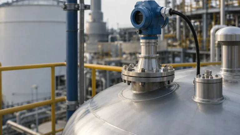
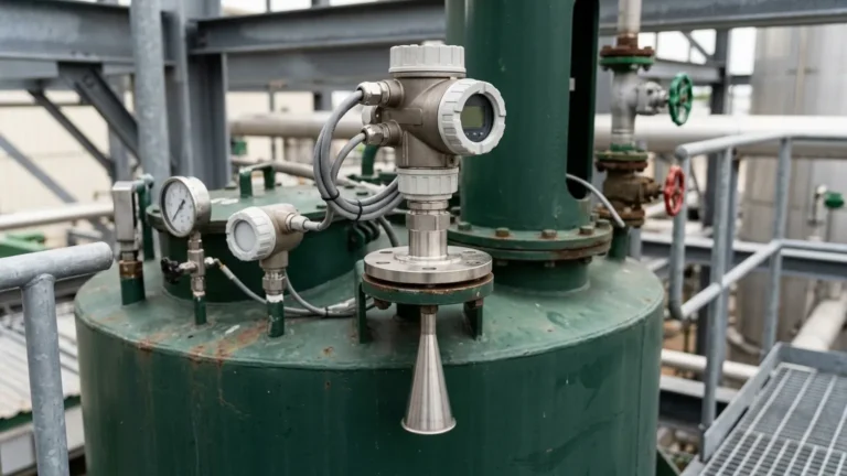
Ultrasonic Radar Type Level Transmitter
Ultrasonic Radar Type Level Transmitter: A Technical Engineering Guide
In the landscape of industrial process automation, selecting the correct non-contact level measurement technology is critical for operational safety and efficiency. The term "ultrasonic radar type level transmitter" is frequently used by procurement professionals and plant engineers to describe non-contact, continuous level measurement solutions. While ultrasonic and radar technologies rely on different physical principles—sound waves versus electromagnetic waves—they share the common goal of providing precise distance measurements without making physical contact with the process media.
This guide explores the technical foundations of these technologies, provides a comparative analysis for selection, and outlines the installation constraints essential for successful deployment in industries ranging from water treatment to chemical processing.
1. Understanding the Measurement Principles
Before selecting a transmitter, it is essential to understand how each technology interacts with the environment and the process media.
Ultrasonic Level Measurement
Ultrasonic transmitters operate on the Time-of-Flight (ToF) principle using acoustic energy. The sensor's transducer emits a high-frequency sound pulse (typically between 20 kHz and 200 kHz). This pulse travels through the air, reflects off the surface of the medium, and returns to the transducer.
The distance is calculated using the formula:
Distance = (Speed of Sound × Time) / 2
Because the speed of sound is influenced by air temperature, most industrial ultrasonic sensors include an integrated temperature sensor to compensate for variations, ensuring accuracy in fluctuating environments.
Radar Level Measurement
Radar Level Meters also utilize the Time-of-Flight principle but employ high-frequency electromagnetic microwave pulses rather than sound waves. These pulses travel at the speed of light. When the pulse hits a medium with a different dielectric constant (εr) than the air or vapor space, a portion of the energy is reflected back to the antenna.
Modern radar transmitters generally fall into two categories:
1. Pulse Radar: Emits a short microwave pulse and measures the time taken for the return.
2. FMCW (Frequency Modulated Continuous Wave): Emits a continuous signal with a varying frequency. The distance is determined by the frequency difference between the transmitted and received signals, offering significantly higher precision and signal-to-noise ratios.
2. Comparing Ultrasonic and Radar Technologies
While an ultrasonic radar type level transmitter might seem interchangeable in simple applications, their performance diverges sharply under specific process conditions.
Media and Dielectric Constants
Radar technology is highly dependent on the dielectric constant of the material. Materials with high dielectric constants (like water, εr ≈ 80) reflect radar signals very well. Materials with low dielectric constants (like certain oils or solids) may require high-sensitivity FMCW radar. Conversely, ultrasonic sensors are independent of the dielectric constant but are sensitive to the density of the air through which the sound travels.
Atmosphere and Pressure
Ultrasonic waves require a medium (gas/air) to propagate. Consequently, they cannot function in a vacuum. Furthermore, significant changes in gas composition or high pressure can alter the speed of sound, leading to measurement errors. Radar waves are electromagnetic and do not require a medium, making them the preferred choice for vacuum applications or high-pressure reactors.
Temperature Extremes
Ultrasonic transducers are generally limited to temperatures below 100°C (212°F) because the piezo-ceramic elements and the speed-of-sound compensation become less reliable at high temperatures. Radar antennas can be engineered with cooling fins or specialized materials to withstand process temperatures exceeding 400°C (752°F).
3. Key Selection Criteria for Industrial Applications
When evaluating an ultrasonic radar type level transmitter for a specific project, engineers should use the following criteria to narrow down the technology:
* Measurement Range: Ultrasonic sensors are typically effective up to 15–30 meters (49–98 ft), whereas high-frequency radar (80 GHz) can accurately measure distances up to 120 meters (393 ft).
* Process Turbulence: If the liquid surface is highly turbulent or covered in thick foam, radar (specifically lower frequency 6 GHz or 26 GHz) often performs better at penetrating the foam, whereas ultrasonic signals may be completely absorbed or scattered.
* Vapor and Dust: Heavy steam or dust can attenuate ultrasonic sound waves. Radar, particularly at lower frequencies, can penetrate these atmospheres with minimal signal loss.
* Cost vs. Performance: For simple, ambient-pressure water tank applications, ultrasonic transmitters remain the most cost-effective solution. However, as process complexity increases, the reliability of radar often justifies the higher initial investment.
4. Practical Selection Table for Engineers
The following table provides a quick reference for technology selection based on common industrial variables.
| Feature | Ultrasonic Transmitter | Radar (26 GHz / 80 GHz) |
| :— | :— | :— |
| Medium | Liquids and Slurries | Liquids, Solids, Corrosives |
| Vacuum Compatibility | No | Yes |
| Max Temperature | ~95°C (203°F) | Up to 450°C (842°F) |
| Max Pressure | ~3 bar (43 psi) | Up to 160 bar (2320 psi) |
| Accuracy | 0.25% of range | Up to ±1 mm |
| Effect of Dust/Vapor | High (Signal loss) | Minimal |
| Dielectric Sensitivity | None | High (Requires εr > 1.4) |
| Cost | Lower | Moderate to Higher |
5. Installation Best Practices and Constraints
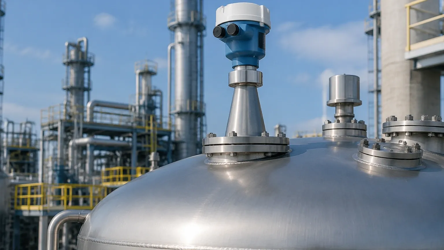
Even the most advanced ultrasonic radar type level transmitter will fail if installation constraints are ignored. Proper mounting ensures that the signal path is clear of obstructions.
The Blocking Distance (Dead Zone)
Every non-contact sensor has a "blocking distance" or "dead zone" directly beneath the sensor face where measurements cannot be taken. For ultrasonic sensors, this is typically 0.2m to 0.5m (0.6ft to 1.6ft). For radar, it is often much smaller (under 0.1m). The sensor must be mounted high enough so that the maximum liquid level never enters this zone.
Beam Angle and Nozzle Mounting
The "beam angle" defines the spread of the signal.
* Ultrasonic: Typically has a wider beam angle (10°–15°).
* 80 GHz Radar: Offers a very narrow beam angle (as low as 3°).
A narrow beam angle is preferable when mounting in tanks with internal obstructions like ladders, agitators, or heating coils. If the sensor is mounted on a nozzle, the nozzle's height and diameter must be checked to ensure the signal does not reflect off the nozzle's internal edges before reaching the tank.
Positioning
* Avoid the Center: Do not mount the transmitter in the exact center of a circular tank, as this can cause multiple reflections (standing waves) that interfere with the signal.
* Avoid the Inflow: Never mount the sensor directly above the point where the tank is filled. The falling stream will create false echoes and signal noise.
* Perpendicularity: Ensure the sensor face is perfectly perpendicular to the liquid surface to maximize the strength of the return echo.
6. Environmental Limitations and Signal Interference
Engineers must account for environmental factors that can degrade signal integrity:
1. Foam: Heavy, dense foam (like protein foam) can absorb both ultrasonic and radar signals. In these cases, a Guided Wave Radar (GWR) or a mechanical magnetic level gauge may be required.
2. Condensation: Droplets on the sensor face can refract the signal. Selecting a radar with a PTFE (Teflon) lens or an ultrasonic sensor with a self-cleaning face can mitigate this.
3. Wind: In outdoor, open-channel flow applications, strong winds can "blow" the ultrasonic sound wave away from the receiver. Radar is unaffected by wind.
7. Frequently Asked Questions (FAQs)
Q: Can I use an ultrasonic transmitter for flammable liquids?
A: Yes, provided the unit is ATEX or IECEx certified for hazardous areas. However, radar is often preferred for volatile organic compounds (VOCs) because the vapors can change the speed of sound, affecting ultrasonic accuracy.
Q: Why is 80 GHz radar becoming more popular than ultrasonic?
A: 80 GHz radar offers a much smaller antenna size, a narrower beam, and higher precision. It can "see" past internal tank obstructions that would block an ultrasonic or lower-frequency radar signal.
Q: Does the color of the liquid affect the measurement?
A: No. Both ultrasonic and radar technologies are independent of the optical properties (color, transparency) of the medium.
Q: How do I handle a tank with a heavy agitator?
A: Use a radar transmitter with a narrow beam angle and utilize the "false echo suppression" software feature. This allows the transmitter to map out the fixed reflections from the agitator blades and ignore them during operation.
Conclusion
Selecting between an ultrasonic and a radar type level transmitter requires a thorough analysis of the process environment. While ultrasonic sensors provide a reliable and cost-effective solution for benign liquid storage and water treatment, radar technology—particularly high-frequency FMCW radar—offers the versatility needed for complex chemical reactions, high-temperature vessels, and precision inventory management. By adhering to strict installation guidelines and understanding the physical limitations of each wave type, engineers can ensure long-term reliability in their level measurement systems.
For specific hardware configurations and technical datasheets, engineers should Review product options and application support to match the instrument to their unique process requirements.