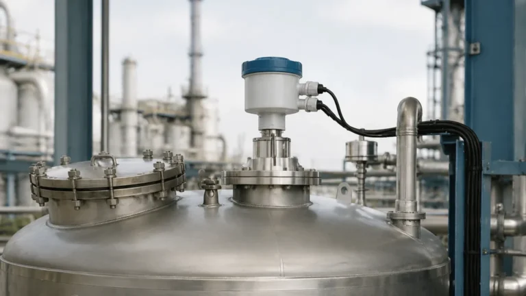
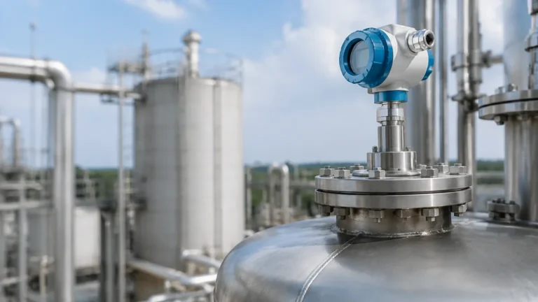
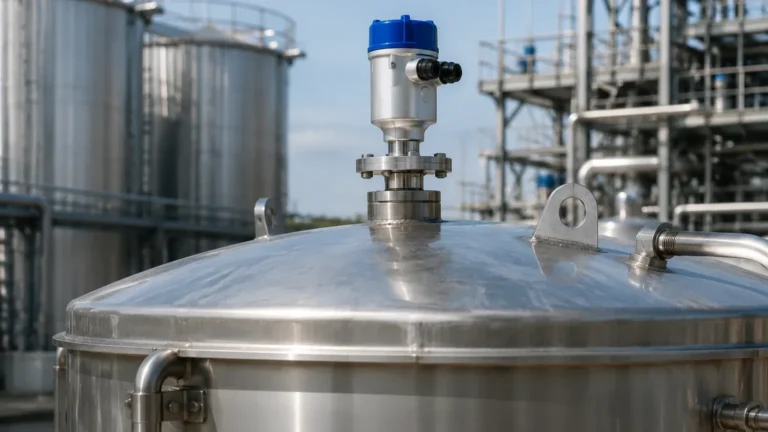
Vegapuls 63 Radar Level Transmitter
Vegapuls 63 Radar Level Transmitter: Engineering Guide for Corrosive Applications
In industrial process automation, selecting the correct instrumentation for level measurement in aggressive media is a critical engineering decision. The vegapuls 63 radar level transmitter is specifically designed to address the challenges of measuring liquid levels in storage tanks and process vessels containing corrosive chemicals, acids, or ultra-pure liquids. As a non-contact measurement solution, it minimizes maintenance requirements by isolating the electronic components from the process environment.
This guide examines the technical specifications, operating principles, and installation requirements for the Vegapuls 63, providing a factual reference for engineers and procurement professionals evaluating Radar Level Meters for harsh industrial environments.
1. Measurement Principle: Pulse Radar Technology
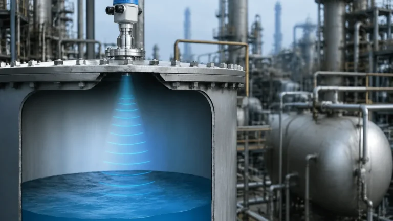
The Vegapuls 63 operates on the principle of non-contact pulse radar. Unlike guided wave radar (GWR), which requires a probe to be in physical contact with the medium, pulse radar transmits high-frequency microwave signals through the air (or vapor space) toward the product surface.
The Time-of-Flight (ToF) Method
1. Signal Emission: The sensor's antenna emits short radar pulses, typically in the K-band frequency range (approximately 26 GHz).
2. Reflection: These pulses travel at the speed of light. When they reach the surface of the measured medium, a portion of the energy is reflected back toward the sensor. The strength of this reflection is primarily determined by the dielectric constant ($ε_r$) of the medium.
3. Signal Processing: The transmitter's electronics measure the time interval between the emission and the reception of the pulse.
4. Distance Calculation: The distance ($D$) is calculated using the formula:
$D = (c × t) / 2$
where $c$ is the speed of light and $t$ is the measured transit time. The level is then derived by subtracting the distance from the known total height of the vessel.
Because radar waves do not require a medium for propagation, the measurement is largely independent of changes in process temperature, pressure, or the presence of vapors and dust, provided the antenna remains clean and unobstructed.
2. Technical Characteristics of the Vegapuls 63
The defining feature of the vegapuls 63 radar level transmitter is its antenna design. To survive in environments involving hydrochloric acid, sulfuric acid, or caustic soda, the unit features a completely encapsulated antenna system.
Material Construction
The antenna is typically encapsulated in PTFE (Polytetrafluoroethylene) or PFA (Perfluoroalkoxy alkanes). These fluoroplastics offer near-universal chemical resistance and a smooth surface that resists product buildup. The flange or process connection is also typically protected by a plastic plate or coating, ensuring that no metallic parts of the instrument come into contact with the corrosive process atmosphere.
Performance Specifications
* Measuring Range: Up to 35 meters (approx. 115 feet).
* Accuracy: Typically within ±2 mm (0.08 inches).
* Process Temperature: -40°C to +150°C (-40°F to +302°F).
* Process Pressure: -1 to +16 bar (-100 to +1600 kPa / -14.5 to +232 psi).
* Frequency: 26 GHz (K-band), which provides a focused beam angle compared to lower frequency 6 GHz sensors, allowing for use in smaller vessels.
3. Industrial Application Engineering
When selecting between various Radar Level Meters, engineers must match the sensor's physical properties to the specific application. The Vegapuls 63 is optimized for the following sectors:
Chemical and Petrochemical
In bulk chemical storage, the sensor is used for monitoring levels in tanks containing aggressive reagents. The PTFE encapsulation prevents the corrosion of the antenna, which is a common failure mode for stainless steel sensors in these environments.
Pharmaceutical and Food Industry
The hygienic versions of the Vegapuls 63 feature gap-free designs and materials that comply with FDA and 3-A sanitary standards. Because the measurement is non-contact, there is no risk of contaminating the product, and the encapsulated antenna can withstand Clean-in-Place (CIP) and Sterilization-in-Place (SIP) cycles.
Water and Wastewater Treatment
For the storage of flocculants, acids for pH adjustment, and sodium hypochlorite, the Vegapuls 63 provides a reliable alternative to ultrasonic sensors, which can be affected by temperature gradients and wind in outdoor installations.
4. Technical Selection Criteria
To ensure successful deployment, the following table provides a comparison of selection factors for radar transmitters in liquid applications:
| Selection Factor | Vegapuls 63 (Encapsulated) | Standard Horn Antenna Radar | Guided Wave Radar (GWR) |
| :— | :— | :— | :— |
| Media Type | Corrosive liquids, high purity | Non-corrosive liquids, oils | Liquids, solids, interface |
| Contact Type | Non-contact | Non-contact | Contact (Probe) |
| Dielectric Constant | ε_r ≥ 1.6 | ε_r ≥ 1.6 | ε_r ≥ 1.4 |
| Maintenance | Very Low | Low | Moderate (Probe cleaning) |
| Vessel Internals | Sensitive to obstructions | Sensitive to obstructions | Less sensitive |
| Foam Handling | Moderate | Moderate | Good |

5. Installation Guidelines and Constraints
Proper mechanical installation is paramount for the accuracy of any radar level meter. For the vegapuls 63 radar level transmitter, engineers should adhere to the following constraints:
Nozzle Geometry
The antenna should ideally extend beyond the bottom of the mounting nozzle. If the nozzle is long and narrow, internal reflections (ringing) can interfere with the signal. If the antenna must be recessed within a nozzle, the nozzle's inner surface must be smooth and free of burrs or welds.
Beam Angle and Obstructions
The 26 GHz signal spreads in a cone-like shape. The installation site must be chosen so that the "signal beam" does not intersect with vessel internals such as ladders, agitators, or heating coils. If an obstruction is unavoidable, most modern transmitters allow for a "False Signal Suppression" or "Static Mapping" to be performed, where the device learns to ignore fixed echoes from internal structures.
Orientation
* Parallelism: The sensor should be mounted so that the antenna is perpendicular to the liquid surface. A slight tilt can significantly reduce the strength of the returned echo, especially in low-dielectric liquids.
* Wall Distance: Do not mount the sensor too close to the vessel wall. A minimum distance of 200 mm (approx. 8 inches) is generally recommended to avoid interference from wall reflections.
6. Limitations and Risk Mitigation
While highly versatile, radar technology has physical limitations that must be addressed during the design phase:
* Low Dielectric Media: Liquids with very low dielectric constants (e.g., liquid nitrogen or certain hydrocarbons) reflect very little energy. In these cases, a larger antenna or a different frequency may be required.
* Heavy Foam: Dense, thick foam can absorb the radar signal entirely, leading to a loss of echo. If heavy foam is expected, guided wave radar or a mechanical level gauge may be more appropriate.
* Vessel Geometry: In spherical or horizontal cylindrical tanks, the signal can be reflected away from the sensor at certain levels. Proper positioning and the use of a stilling well can mitigate these geometry-related issues.
7. Procurement and Technical Confirmation
International buyers and engineers should confirm the following data points with the manufacturer before finalizing a purchase of a vegapuls 63 radar level transmitter:
1. Media Properties: Confirm the dielectric constant and the potential for foam or agitation.
2. Process Connection: Specify flange size (e.g., DN50, ANSI 2") and material (e.g., PP, PTFE, or 316L with a PTFE plate).
3. Output Requirements: Standard 4-20 mA HART is common, but Profibus PA or Foundation Fieldbus may be required for integrated automation systems.
4. Hazardous Area Ratings: Ensure the device carries the necessary ATEX, IECEx, or FM certifications for the specific zone of installation.
8. Frequently Asked Questions (FAQ)
Q: Can the Vegapuls 63 measure through a plastic tank lid?
A: Yes. Since radar waves pass through non-conductive materials, it is possible to measure through a plastic or fiberglass tank roof without a process penetration, provided the material is not too thick and does not contain conductive reinforcements.
Q: How does the Vegapuls 63 handle condensation?
A: The encapsulated antenna is designed so that droplets of condensation naturally run off the convex surface. However, heavy, continuous condensation can still attenuate the signal. In extreme cases, a version with a rinsing connection (air purge) may be used to keep the antenna face clear.
Q: What is the difference between the Vegapuls 63 and the Vegapuls 64?
A: The Vegapuls 63 is a 26 GHz sensor often used for chemical applications due to its robust encapsulation. The Vegapuls 64 is an 80 GHz sensor. The higher frequency of the 64 allows for a much narrower beam and smaller process connections, but the 63 remains a standard for specific aggressive chemical environments where 26 GHz technology is well-proven.
Q: Is a stilling well necessary?
A: A stilling well is not required for the Vegapuls 63 in most applications. However, if there is extreme surface turbulence or if the dielectric constant of the liquid is very low, a stilling well can help focus the signal and provide a stable surface for measurement.
By understanding these engineering principles and installation requirements, process operators can ensure that their Radar Level Meters provide accurate, maintenance-free service throughout the lifecycle of the industrial plant.