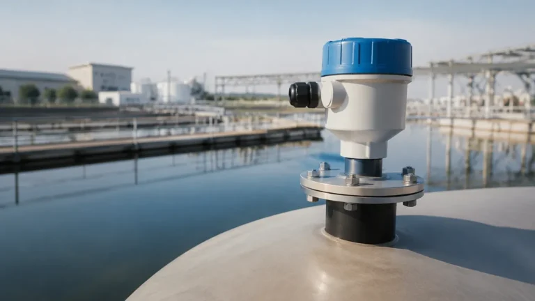
Ultrasonic Level Sensor Installation Guide
Ultrasonic Level Sensor Installation Guide: Engineering Best Practices
In the realm of industrial process control, accurate level measurement is fundamental to operational efficiency, safety, and inventory management. Among the various technologies available, ultrasonic level measurement has emerged as a preferred non-contact solution for a wide range of liquid and solid applications. However, the performance of these instruments is heavily dependent on correct selection and precise mounting. This guide provides a comprehensive technical overview of the principles, selection criteria, and a detailed ultrasonic level sensor installation guide to ensure reliable performance in industrial environments.
Understanding Ultrasonic Level Measurement Principles
Before proceeding with installation, it is essential to understand the physics governing Ultrasonic Level Meters. These devices operate on the Time-of-Flight (ToF) principle.
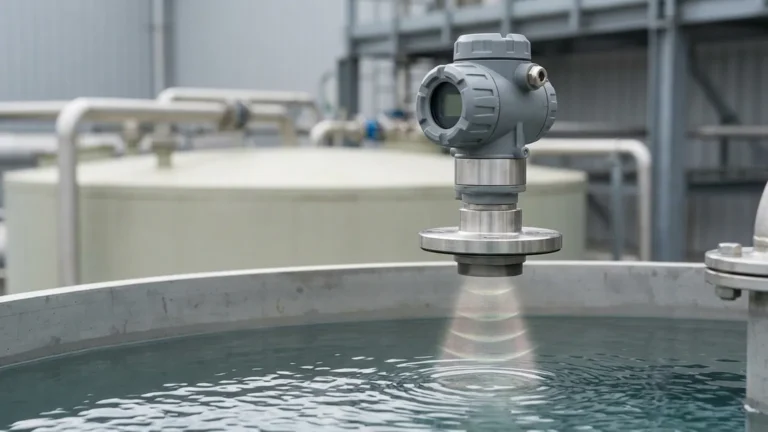
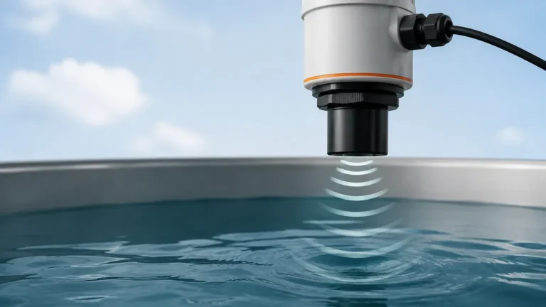
The sensor's transducer emits a high-frequency ultrasonic pulse (typically between 20 kHz and 70 kHz). This sound wave travels through the air space above the medium, hits the surface of the material, and reflects back to the transducer. The instrument then measures the time interval between the emission of the pulse and the reception of the echo.
The distance ($D$) from the sensor to the material surface is calculated using the formula:
$$D = \frac{c \times t}{2}$$
Where:
- $c$ is the speed of sound in the medium (typically air).
- $t$ is the measured time-of-flight.
Because the speed of sound is affected by air temperature (increasing by approximately 0.6 m/s per degree Celsius), professional-grade meters, such as those manufactured by Welk, incorporate integrated temperature sensors to compensate for these fluctuations automatically. Without this compensation, a 10°C temperature shift could result in a measurement error of nearly 2%.
Key Selection Criteria for Ultrasonic Level Meters
Selecting the appropriate instrument is the first step toward a successful installation. Engineers must evaluate the following factors to ensure the sensor matches the application requirements:
1. Measurement Range: Sensors are rated for specific maximum and minimum distances. A sensor designed for a 10-meter (32.8 ft) range may struggle with signal strength if used in a 15-meter (49.2 ft) silo.
2. Beam Angle: The ultrasonic pulse spreads as it travels, forming a cone. A narrower beam angle is preferable for tall, narrow tanks or vessels with internal obstructions like ladders or agitators.
3. Frequency: Higher frequency sensors (e.g., 60 kHz) are generally more compact and offer higher resolution but have shorter ranges. Lower frequency sensors (e.g., 20 kHz) penetrate dust and vapor more effectively and cover longer distances.
4. Process Conditions: Consider the presence of foam, heavy vapor, or extreme turbulence, all of which can absorb or scatter the ultrasonic signal.
Practical Selection Table
| Application Type | Recommended Range | Frequency | Housing Material |
| :— | :— | :— | :— |
| Standard Water Tank | 0.3m – 10m | 40-50 kHz | ABS / PVC |
| Chemical Storage | 0.4m – 15m | 40 kHz | PVDF / PTFE |
| Large Silos (Solids) | 1m – 30m | 20 kHz | Aluminum / Stainless Steel |
| Open Channel Flow | 0.2m – 5m | 60-70 kHz | UV-Resistant Plastic |
Comprehensive Ultrasonic Level Sensor Installation Guide
The reliability of an ultrasonic measurement system is often determined by the physical placement of the sensor. Following this ultrasonic level sensor installation guide will help mitigate common signal interference issues.
1. Mounting Position and Orientation
The transducer face must be mounted perfectly parallel to the liquid surface. If the sensor is tilted, the ultrasonic pulse will reflect away from the transducer rather than back to it, resulting in a "Loss of Echo" error. For solid materials with a repose angle, an adjustable flange may be required to aim the sensor at the most representative point of the pile.
2. Managing the Dead Zone (Blocking Distance)
Every ultrasonic sensor has a "dead zone" directly beneath the transducer where it cannot process an echo. This is due to the time required for the transducer to stop vibrating (ringing) after emitting a pulse before it can switch to receiving mode.
- Requirement: Ensure the maximum liquid level never reaches into the dead zone.
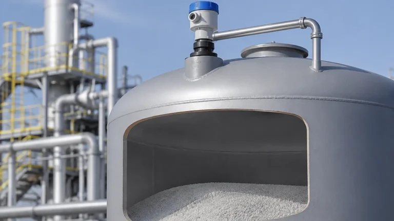
- Solution: If the tank must be filled to the very top, mount the sensor on a nozzle or a stand-off pipe to elevate the dead zone above the maximum fill line.
3. Avoiding Internal Obstructions and the "Rule of 1/6th"
To prevent false echoes from tank walls or internal structures, the sensor should be placed at a distance from the wall approximately equal to 1/6th of the tank's height.
- Wall Interference: Mounting too close to a flat wall can cause the beam to reflect off the wall and back to the sensor, creating a false high-level reading.
- Obstructions: The beam path must be clear of ladders, pipes, heating coils, or agitator blades. If an obstruction is unavoidable, many Welk ultrasonic meters offer "false echo suppression" software to ignore these static reflections.
4. Filling Inlets and Turbulence
Never mount the sensor directly above the filling inlet. The falling stream of liquid or granules will reflect the ultrasonic signal before it reaches the actual level, leading to erratic readings. Furthermore, if the filling process creates significant foam or surface turbulence, the sensor should be mounted in a stilling well (a vertical pipe with vent holes) to provide a calm surface for measurement.
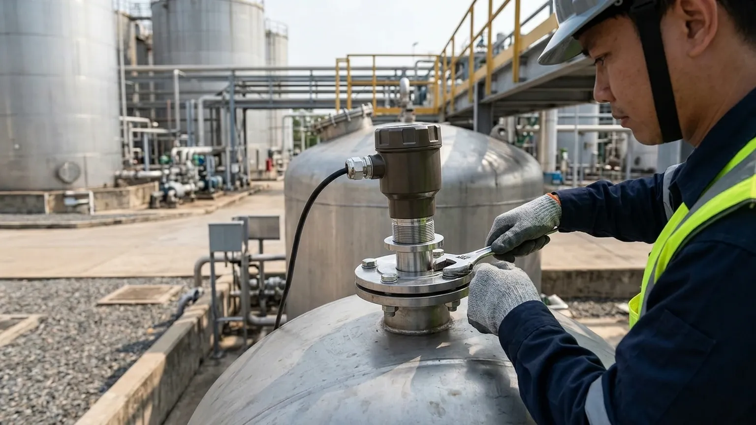
5. Nozzle Considerations
When mounting on a nozzle, the diameter and height of the nozzle are critical. If the nozzle is too narrow or too long, the ultrasonic beam will hit the nozzle walls, creating a strong false echo. Ideally, the transducer face should extend 10mm to 20mm (0.4 to 0.8 inches) below the bottom of the nozzle into the tank.
Application-Specific Installation Considerations
Outdoor and High-Temperature Environments
For outdoor installations, such as open-channel flow measurement or reservoir monitoring, the sensor is exposed to direct sunlight. This can cause the internal temperature sensor to read higher than the actual air temperature through which the sound travels. A sunshade or weather shield is highly recommended to maintain accuracy.
Chemical and Corrosive Storage
In tanks containing acids or volatile organic compounds (VOCs), the sensor housing must be chemically compatible. PVDF or PTFE-coated transducers are standard for these applications. Additionally, ensure that the cable entry points are sealed with appropriate glands to prevent corrosive vapors from entering the electronics housing.
Technical Limitations and Environmental Factors
While Ultrasonic Level Meters are versatile, they are not suitable for every environment. Understanding these limitations is crucial for engineering design:
- Vacuum Applications: Sound waves require a medium (air or gas) to travel. In a vacuum, ultrasonic sensors cannot function.
- High Pressure: Extremely high pressure (typically above 3 bar) can change the density of the gas, affecting the speed of sound and signal attenuation beyond the range of standard compensation.
- Heavy Foam: Light, airy foam is an excellent sound absorber. If the foam layer is thick enough, the pulse may never return to the sensor. In such cases, a contact-based technology like a magnetic level gauge or a hydrostatic transmitter may be more appropriate.
- Heavy Dust or Steam: While lower frequencies can penetrate some dust, extreme concentrations in silos or heavy steam in boilers can scatter the signal, reducing the effective range.
Maintenance and Troubleshooting FAQs
Q: Why is my sensor reading "Full" when the tank is empty?
A: This is often caused by a false echo from a nozzle or an internal obstruction near the top of the tank. Check the mounting position and ensure the transducer face is clear. You may need to use the instrument’s "Map False Echo" function.
Q: How do I handle condensation on the transducer face?
A: Condensation can attenuate the signal. Many Welk sensors feature a self-cleaning effect due to the vibration of the transducer, but in extreme cases, mounting the sensor at a slight angle (less than 3 degrees) or using a sensor with a PTFE face can help moisture bead off.
Q: Can I use an ultrasonic sensor in a tank with an agitator?
A: Yes, provided the sensor is mounted away from the path of the blades. Most modern controllers allow you to set a damping or averaging filter to ignore the momentary interference caused by the rotating blades.
Q: What is the maximum cable length for a remote-mounted sensor?
A: For split-type ultrasonic meters, the cable between the probe and the electronic unit can typically extend up to 50–100 meters (164–328 ft), provided shielded twisted-pair cabling is used to prevent electromagnetic interference.
Conclusion
Successful level measurement starts with a thorough understanding of the application and adherence to a strict ultrasonic level sensor installation guide. By considering the beam angle, avoiding the dead zone, and ensuring a clear path to the material surface, engineers can leverage the benefits of non-contact ultrasonic technology—low maintenance, high accuracy, and long-term reliability. For complex applications involving extreme temperatures or chemical compatibility, consulting with a specialized manufacturer like Welk ensures that the selected instrument and installation strategy are optimized for the specific process requirements.
Download Ultrasonic Level Sensor Installation Guide as a PDF