Ultrasonic Level Sensor Emerson
A Comprehensive Engineering Guide to Ultrasonic Level Meters and Industrial Sensors
In the field of industrial automation, selecting the correct level measurement technology is critical for operational efficiency, safety, and cost control. Among the various non-contact methods available, Ultrasonic Level Meters have become a standard solution for liquid and solid monitoring across water treatment, chemical processing, and food production. This guide explores the technical principles, selection criteria, and practical application of these instruments, including insights into market-leading solutions like the ultrasonic level sensor emerson (Rosemount) series and comparable industrial alternatives.
1. Understanding the Measurement Principle
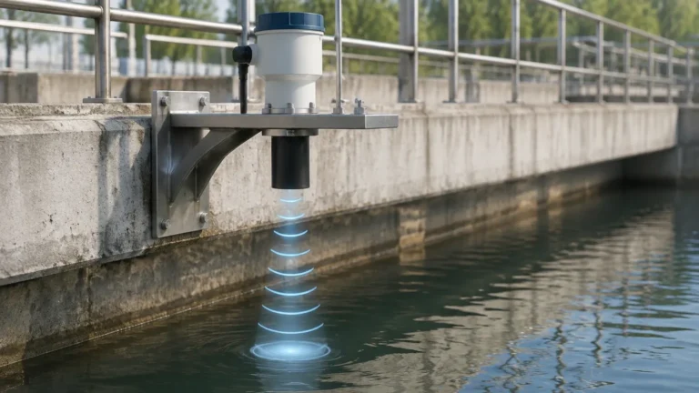
Ultrasonic level measurement is based on the "Time-of-Flight" (ToF) principle. The sensor, typically mounted at the top of a vessel, contains a piezoelectric crystal that converts electrical energy into mechanical energy in the form of high-frequency sound pulses.
The Calculation Process
1. Emission: The transducer emits an ultrasonic pulse toward the surface of the medium.
2. Reflection: The pulse hits the surface and is reflected back to the sensor.
3. Detection: The transducer acts as a receiver, detecting the returning echo.
4. Calculation: The internal electronics measure the time interval ($t$) between emission and reception. Using the known speed of sound in air ($c$), the distance ($D$) is calculated using the formula:
$$D = \frac{c \times t}{2}$$
The level of the material is then determined by subtracting this distance from the total tank height (the calibration span). Because the speed of sound is affected by air temperature, modern Ultrasonic Level Meters include integrated temperature sensors to compensate for these variations automatically, ensuring accuracy within $\pm$0.25% of the measured range.
2. Evaluating the Ultrasonic Level Sensor Emerson Series
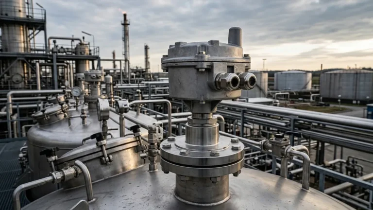
When engineers discuss the ultrasonic level sensor emerson line, they are typically referring to the Rosemount brand. These sensors, such as the Rosemount 3100 series, are recognized for their reliability in harsh environments. They often feature advanced software algorithms designed to filter out "false echoes" caused by internal tank obstructions like agitators or ladders.
For B2B procurement, comparing these premium solutions against specialized industrial manufacturers like Welk is essential. While Emerson provides a broad ecosystem of HART and Foundation Fieldbus compatible devices, many industrial applications in water treatment and chemical storage require the same level of precision and ruggedness at a more optimized cost-to-performance ratio. Modern alternatives now offer similar Digital Signal Processing (DSP) capabilities, enabling them to distinguish between the true material level and parasitic reflections in complex vessel geometries.
3. Technical Selection Criteria
Choosing the right sensor requires a detailed analysis of the application environment. The following table provides a general selection matrix for industrial-grade ultrasonic transmitters.
| Feature | Specification Range | Engineering Consideration |
| :— | :— | :— |
| Measurement Range | 0.3m to 30m | Ensure the maximum range exceeds tank height by 20%. |
| Dead Zone (Blocking Distance) | 0.2m to 0.6m | The area directly below the sensor where measurement is impossible. |
| Output Signal | 4-20mA, RS485 (Modbus), HART | Compatibility with existing PLC/SCADA systems. |
| Process Temperature | -40°C to +70°C | High temperatures can fluctuate sound speed significantly. |
| Process Pressure | 0.5 Bar to 3 Bar | Ultrasonic waves do not travel in a vacuum. |
| Beam Angle | 5° to 12° | Narrower beams are better for narrow tanks with internal structures. |
| Enclosure Rating | IP66, IP67, or IP68 | Necessary for outdoor or wash-down environments. |
4. Installation Best Practices
Correct installation is the most significant factor in the performance of an ultrasonic level sensor emerson or any equivalent ultrasonic device. Failure to follow geometric constraints often leads to signal loss or erratic readings.
Placement and Orientation
* Avoid the Center: Never mount the sensor in the exact center of a circular tank. This can cause multiple reflections to converge, creating a false signal amplification that confuses the processor.
* Perpendicular Alignment: The transducer face must be perfectly parallel to the liquid surface. A tilt of even a few degrees can cause the reflected signal to miss the receiver entirely.
* Inflow Interference: Do not install the sensor above the fill stream. The turbulence and falling material will scatter the ultrasonic pulses.
* Wall Clearance: Maintain a distance from the tank wall of at least 1/10th of the total height to prevent interference from wall seams or weld beads.
The Dead Zone (Blocking Distance)
Every ultrasonic sensor has a "dead zone" immediately below the transducer where the crystal is still vibrating from the emission and cannot yet receive an echo. If the liquid level enters this zone, the sensor will report an error or a fixed maximum value. Engineers must ensure the sensor is mounted high enough (often using a nozzle or standpipe) so that the maximum liquid level never reaches the dead zone.
5. Operational Limitations and Environmental Factors
While Ultrasonic Level Meters are versatile, they are not universal solutions. Certain process conditions interfere with the physics of sound propagation:
1. Heavy Foam: Foam acts as an acoustic absorber. If the surface is covered in thick, light foam, the ultrasonic pulse may be absorbed rather than reflected, resulting in a "Loss of Echo" (LOE) error.
2. Vapors and Dust: High concentrations of solvent vapors or heavy dust can change the density of the air medium, altering the speed of sound and introducing measurement errors. In such cases, radar level meters are often preferred.
3. Vacuum Conditions: Sound requires a medium to travel. In a vacuum or near-vacuum environment, ultrasonic sensors cannot function.
4. High Pressure: In high-pressure gas environments, the increased density of the gas can significantly attenuate the ultrasonic signal, reducing the effective range of the sensor.
6. Maintenance and Troubleshooting
One of the primary benefits of non-contact ultrasonic technology is the minimal maintenance required, as there are no moving parts to wear out or probes to coat. However, a routine inspection schedule should include:
* Transducer Cleaning: In applications with high humidity or condensation, water droplets may form on the transducer face. While many sensors feature a self-cleaning vibration effect, heavy buildup or crystallization from chemical vapors should be gently wiped away with a soft cloth.
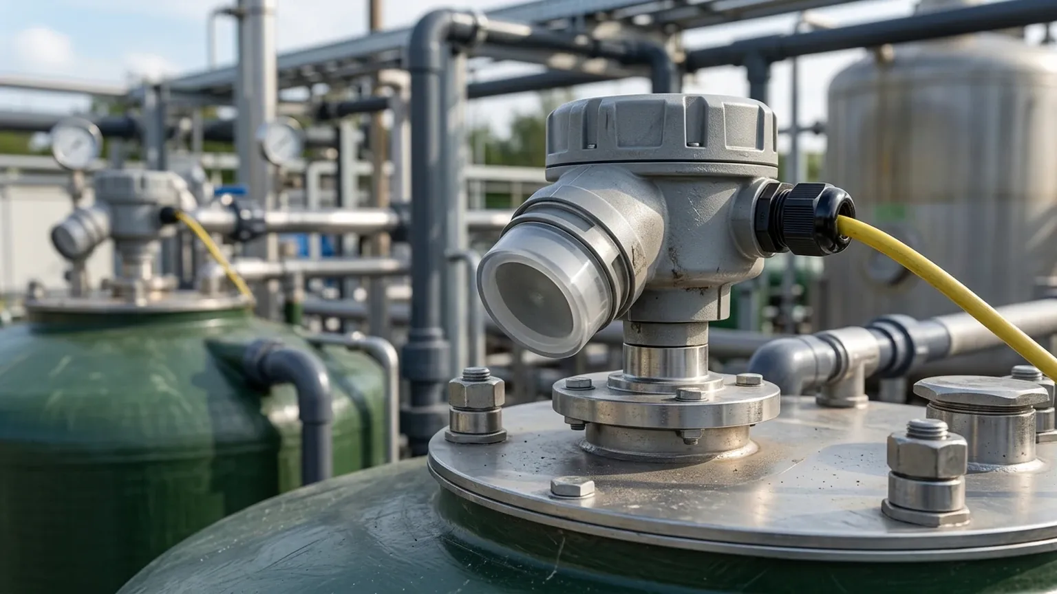
* Cable Integrity: Ensure that cable glands are tight and that there is no moisture ingress in the terminal housing, which is a common cause of 4-20mA signal drift.
* Diagnostic Logs: If using a smart ultrasonic level sensor emerson or a Welk digital transmitter, check the signal strength (echo profile). A weakening signal over time may indicate environmental changes or the need for sensor recalibration.
7. Frequently Asked Questions (FAQ)
Q: Can ultrasonic sensors measure solids like grain or sand?
A: Yes, but with limitations. Solids do not reflect sound as efficiently as liquids and often have an uneven surface (angle of repose). For solids, it is recommended to use a sensor with a higher power output and a wider beam angle, and to derate the effective range by approximately 50%.
Q: How do I handle condensation on the sensor face?
A: Many industrial Ultrasonic Level Meters are designed with a convex transducer face to shed droplets. If condensation is persistent, installing the sensor in a heated housing or using a model with a higher acoustic power can help penetrate the moisture layer.
Q: Is it possible to use ultrasonic sensors in hazardous areas?
A: Yes, many models are available with ATEX, IECEx, or FM certifications for use in explosive atmospheres. These are typically "Intrinsically Safe" (Ex ia) or "Explosion Proof" (Ex d) rated.
Q: What is the difference between an ultrasonic transmitter and an ultrasonic switch?
A: A transmitter provides a continuous measurement (e.g., 4-20mA) of the level, whereas a switch only provides a discrete signal (on/off) when the material reaches a specific point.
Conclusion
Whether integrating an ultrasonic level sensor emerson for a high-spec petrochemical project or deploying a fleet of Ultrasonic Level Meters for municipal water management, understanding the relationship between acoustic physics and vessel geometry is paramount. By respecting the dead zone, ensuring proper alignment, and accounting for environmental factors like foam and pressure, engineers can achieve highly reliable, maintenance-free level monitoring. For specific application support or to review technical datasheets for your next project, consult with a professional instrumentation manufacturer to ensure the technology matches your process requirements.