Ultrasonic Level Sensor Connection Diagram
Ultrasonic Level Sensor Connection Diagram: A Technical Guide for Industrial Integration
In the landscape of industrial automation, precise liquid and solid level monitoring is foundational to operational efficiency. Among the various technologies available, Ultrasonic Level Meters have emerged as a preferred choice due to their non-contact nature, versatility, and cost-effectiveness. However, the reliability of these instruments depends not only on the quality of the sensor but also on correct electrical integration. Understanding a comprehensive ultrasonic level sensor connection diagram is essential for engineers and technicians to ensure accurate data transmission and long-term instrument stability.
This guide explores the fundamental measurement principles of ultrasonic technology, details the various wiring configurations found in modern industrial environments, and provides practical selection and installation criteria for successful deployment.
Measurement Principles of Ultrasonic Level Meters
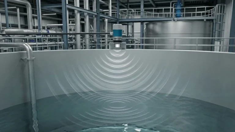
Before diving into the specifics of an ultrasonic level sensor connection diagram, it is vital to understand how these devices function. Ultrasonic level measurement is based on the "Time-of-Flight" (ToF) principle.
The sensor's transducer emits a high-frequency acoustic pulse—typically between 20 kHz and 200 kHz. This sound wave travels through the air at the speed of sound, hits the surface of the target material (liquid or solid), and reflects back to the transducer. The instrument then measures the time elapsed between the emission of the pulse and the reception of the echo.
The distance ($D$) from the sensor to the material surface is calculated using the formula:
$D = (c \times t) / 2$
Where:
* $c$ is the speed of sound in the medium (adjusted for temperature).
* $t$ is the total time elapsed for the round trip.
By knowing the total height of the tank or vessel ($H$), the device calculates the actual level ($L$) as: $L = H – D$.
Because the speed of sound is influenced by air temperature, most professional Ultrasonic Level Meters include an integrated temperature sensor to provide real-time compensation, ensuring accuracy even as environmental conditions fluctuate.
Decoding the Ultrasonic Level Sensor Connection Diagram
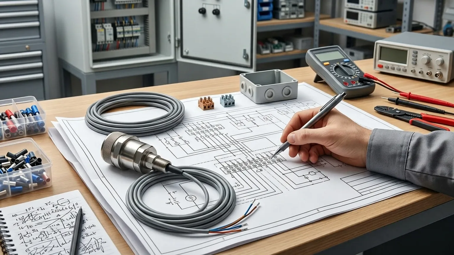
An ultrasonic level sensor connection diagram serves as the blueprint for integrating the device into a wider Control System (PLC, DCS, or SCADA). Depending on the model and application requirements, these sensors typically follow one of three primary wiring architectures.
1. Two-Wire System (Loop-Powered)
In a 2-wire configuration, the same two wires provide the power supply (usually 24V DC) and carry the 4-20mA output signal. This is the most common setup for modern industrial transmitters due to its simplicity and reduced cabling costs.
* Wiring Logic: The sensor acts as a variable resistor in the loop. The PLC/Controller provides the voltage, and the sensor modulates the current between 4mA (empty) and 20mA (full).
* Pros: Lower installation cost, easier troubleshooting.
* Cons: Limited power available for high-power transducers or backlit displays.
2. Three-Wire and Four-Wire Systems
Four-wire systems utilize separate pairs for power supply and signal output. This is often necessary for instruments that require AC power (110V/220V) or those equipped with high-intensity transducers for long-range measurements (up to 30 or 40 meters).
* Wiring Logic: Two wires connect to the power source (AC or DC), and two wires carry the isolated 4-20mA signal to the controller.
* Pros: Higher power availability, galvanic isolation between power and signal.
* Cons: Increased cabling complexity and cost.
3. Digital Communication (RS485/Modbus)
Many advanced sensors now feature digital outputs alongside or instead of analog signals. An ultrasonic level sensor connection diagram for these units will specify the A and B terminals for RS485 Modbus RTU communication.
* Wiring Logic: A twisted-pair shielded cable connects multiple sensors in a daisy-chain configuration to a single master gateway or PLC.
* Pros: High data integrity, ability to transmit diagnostic data (temperature, signal strength), reduced I/O module requirements.
Technical Selection Table
When reviewing an ultrasonic level sensor connection diagram, it is important to match the instrument's electrical capabilities with the project's requirements. Below is a comparison of typical configurations.
| Feature | 2-Wire (DC) | 4-Wire (DC/AC) | Digital (RS485) |
| :— | :— | :— | :— |
| Power Supply | 24V DC (Loop) | 24V DC or 85-265V AC | 12-24V DC |
| Signal Output | 4-20mA | 4-20mA / Relays | Modbus RTU |
| Max Distance | Typically up to 15m | Up to 40m+ | Network dependent |
| Cabling | 1 Twisted Pair | 2 Pairs (or 4 core) | 1 Shielded Pair |
| Complexity | Low | Moderate | Moderate (Software config) |
| Best For | Standard liquid tanks | Solids, deep silos, or remote sites | Multi-tank farms |
Installation Considerations and Best Practices
Correct electrical connection is only half the battle; physical installation significantly impacts the accuracy of the readings. Engineers should consult the ultrasonic level sensor connection diagram in conjunction with these mechanical guidelines:
The Dead Zone (Blanking Distance)
Every ultrasonic sensor has a "Dead Zone" directly beneath the transducer face where measurements are impossible. This is the time required for the transducer to stop vibrating after emitting a pulse so it can listen for the return echo. Typical dead zones range from 0.2m to 0.6m depending on the frequency. Ensure the maximum liquid level never enters this zone.
Beam Angle and Obstructions
The ultrasonic pulse spreads out in a cone (usually 5° to 12°). The ultrasonic level sensor connection diagram documentation will specify this angle. Ensure that the "beam path" is clear of ladders, pipes, or agitators, as these will cause false echoes.
Cable Shielding and Grounding
To prevent Electromagnetic Interference (EMI) from VFDs (Variable Frequency Drives) or high-voltage motors, always use shielded cables. The shield should be grounded at one end only (usually at the control cabinet) to avoid ground loops which can introduce noise into the 4-20mA signal.
Common Risks and Limitations
While highly effective, ultrasonic technology has factual boundaries that must be respected:
1. Vacuum Conditions: Sound waves require a medium to travel. Ultrasonic sensors cannot function in a vacuum.
2. Heavy Foam: Thick, dense foam can absorb the acoustic pulse, leading to a "Loss of Echo" error.
3. High Pressure/Temperature: Extreme temperatures can alter the speed of sound beyond the compensation limits of the internal sensor, and high pressure can change the air density, affecting pulse propagation.
4. Dust and Vapor: While mild dust is manageable, extremely heavy dust (in grain silos) or thick steam can scatter the sound waves.
Frequently Asked Questions (FAQ)
Q: Can I use a standard multi-core cable for the ultrasonic level sensor connection?
A: While possible for short distances, it is highly recommended to use a shielded, twisted-pair cable (e.g., Belden 8760) to protect the 4-20mA or RS485 signal from industrial noise.
Q: What happens if I reverse the polarity in a 2-wire connection?
A: Most professional Ultrasonic Level Meters include reverse polarity protection. The device simply will not power up, but it will not be damaged. Always double-check the ultrasonic level sensor connection diagram before applying power.
Q: How do I handle a "Loss of Echo" (LOE) alarm?
A: First, check the wiring for loose connections. If the wiring is sound, inspect the transducer face for condensation or dirt. Finally, ensure the sensor is mounted perpendicular to the liquid surface.
Q: Can the signal wire be run in the same conduit as power lines?
A: No. Signal cables (4-20mA/RS485) should be kept in separate conduits or at least 30cm away from high-voltage AC power lines to prevent inductive coupling and signal interference.
Conclusion
Successfully implementing an ultrasonic level measurement system requires a disciplined approach to both electrical and mechanical integration. By carefully following the ultrasonic level sensor connection diagram, selecting the appropriate wiring architecture (2-wire vs. 4-wire), and adhering to installation best practices regarding beam angles and dead zones, operators can achieve highly reliable and maintenance-free level monitoring. For complex applications involving hazardous areas or extreme distances, consulting with a specialist manufacturer like Welk ensures that the selected instrumentation meets the specific rigors of the industrial environment.
Download Ultrasonic Level Sensor Connection Diagram as a PDF