Ultrasonic Level Sensor Range
Understanding Ultrasonic Level Sensor Range: A Technical Guide for Industrial Applications
In industrial process control, selecting the correct instrumentation requires a deep understanding of how environmental variables interact with sensor specifications. Among the most critical parameters for non-contact measurement is the ultrasonic level sensor range. This specification determines not only the maximum distance a sensor can monitor but also the "dead zone" near the transducer where measurement is impossible.
For engineers and procurement professionals evaluating Ultrasonic Level Meters, the range is not a static number. It is a dynamic capability influenced by transducer frequency, target material properties, and atmospheric conditions. This guide examines the principles of ultrasonic measurement and provides a framework for selecting the appropriate range for water treatment, chemical processing, and industrial automation.
Measurement Principles of Ultrasonic Technology
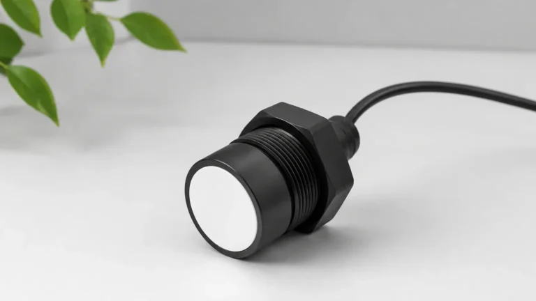
Ultrasonic level measurement is based on the "Time of Flight" (ToF) principle. The sensor’s transducer contains a piezoelectric crystal that converts electrical energy into mechanical vibrations, emitting high-frequency sound pulses toward the target medium.
1. Emission: The transducer emits an ultrasonic pulse.
2. Reflection: The pulse travels through the air, hits the surface of the liquid or solid, and reflects back as an echo.
3. Detection: The transducer receives the returning echo and converts it back into an electrical signal.
4. Calculation: The internal processor calculates the distance based on the formula:
Distance = (Speed of Sound × Time) / 2
The ultrasonic level sensor range is defined by the window between the minimum detectable distance (the blocking distance) and the maximum distance at which the echo remains strong enough to be distinguished from background noise.
Defining the Range: The Near and Far Limits
When reviewing technical datasheets for ultrasonic level meters, two distinct boundaries define the effective range: the Dead Zone and the Maximum Measuring Distance.
1. The Dead Zone (Blocking Distance)
Every ultrasonic sensor has a minimum range, often called the "dead zone" or "blanking distance." This occurs because the transducer cannot transmit and receive simultaneously. After emitting a pulse, the piezoelectric element continues to vibrate (ring down) for a few milliseconds. If an echo returns during this period, the sensor cannot detect it.
Typically, the dead zone is proportional to the transducer's frequency. Lower-frequency sensors (designed for long ranges) have larger dead zones, often between 0.5m and 0.8m (1.6ft to 2.6ft). High-frequency sensors (designed for short ranges) may have dead zones as small as 0.2m (0.6ft).
2. The Maximum Measuring Range
The maximum ultrasonic level sensor range is the furthest distance at which the sensor can reliably detect a return signal. This is primarily governed by the frequency of the sound wave. Sound energy dissipates as it travels through air; lower frequencies travel further with less attenuation than higher frequencies.
* Short Range (0.2m – 5m): High-frequency transducers (approx. 60–75 kHz). Ideal for small tanks and chemical dosing skids.
* Medium Range (0.5m – 15m): Mid-frequency transducers (approx. 40 kHz). Standard for water sumps and storage tanks.
* Long Range (0.8m – 40m): Low-frequency transducers (approx. 20 kHz). Used for deep wells, large reservoirs, and silos.
Factors Influencing Ultrasonic Level Sensor Range
In a laboratory environment, a sensor may achieve its rated maximum range easily. However, in industrial field applications, several factors can significantly reduce the effective distance.
Atmospheric Conditions
* Temperature: The speed of sound in air changes by approximately 0.17% per degree Celsius. While most modern ultrasonic level meters include integrated temperature compensation, extreme temperature gradients can refract the sound beam, reducing the effective range.
* Pressure: Ultrasonic sensors are generally designed for atmospheric pressure. High-pressure environments increase air density, which can improve signal transmission, but the mechanical seals of the transducer must be rated for such conditions.
* Vapors and Gases: The presence of heavy vapors (such as those from solvents) or high concentrations of CO2 changes the medium through which the sound travels, potentially causing measurement errors or signal loss.
Surface Characteristics
* Turbulence: A boiling or highly agitated liquid surface scatters the ultrasonic pulse in multiple directions. This reduces the amount of energy reflected back to the sensor, effectively shortening the usable range.
* Foam: Foam is one of the most challenging obstacles for ultrasonic technology. Light, airy foam absorbs the sound pulse rather than reflecting it. If a thick foam layer is present, the sensor may lose the signal entirely or report an incorrect level.
* Angle of Repose: In solids measurement (e.g., grain or plastic pellets), the material forms a cone. If the angle of the slope is steep, the signal may bounce off the slope and away from the transducer.
Practical Selection Table
The following table provides a general guideline for matching transducer frequency to the required measuring range and application type.
| Transducer Frequency | Typical Max Range | Dead Zone (Approx.) | Common Applications |
| :— | :— | :— | :— |
| 70 kHz | 5 Meters (16.4 ft) | 0.20m – 0.25m | Chemical tanks, small IBCs, indoor sumps |
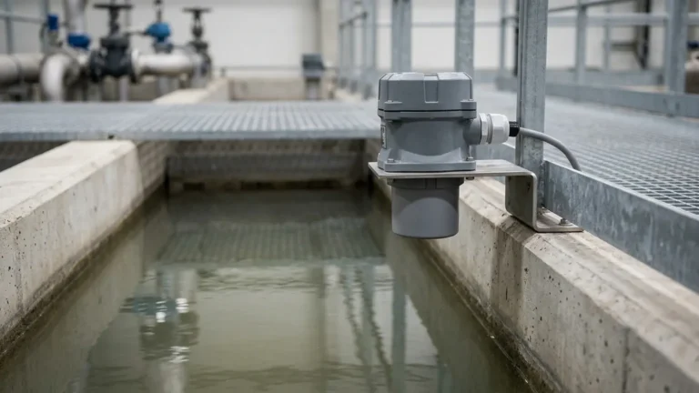
| 40 kHz | 12 – 15 Meters (49 ft) | 0.35m – 0.50m | Water treatment tanks, open channels, pump stations |
| 25 kHz | 25 – 30 Meters (98 ft) | 0.60m – 0.80m | Large reservoirs, wastewater basins, tall silos |
| 20 kHz | 40 Meters (131 ft) | 0.80m – 1.00m | Deep wells, mining pits, large-scale industrial storage |
Installation Considerations for Optimizing Range
To ensure the ultrasonic level sensor range meets the requirements of the project, proper installation is mandatory. Even the highest quality sensor will fail if mounted incorrectly.
Beam Angle and Obstructions
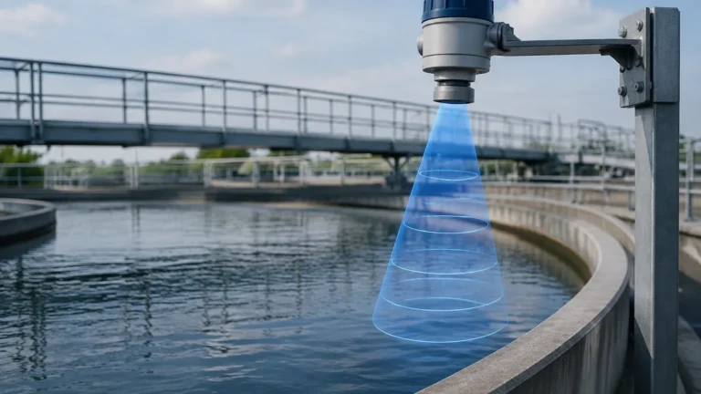
Ultrasonic pulses propagate in a cone shape, typically between 5° and 12°. Any physical obstruction within this cone—such as ladders, pipes, or internal tank braces—will create a "false echo."
* Guideline: Mount the sensor at a distance from the wall at least 1/10th of the total tank height to avoid wall interference.
* Clear Path: Ensure the path between the transducer face and the lowest expected liquid level is completely clear of obstructions.
Mounting Orientation
The transducer face must be perfectly parallel to the liquid surface. A tilt of even a few degrees can cause the reflected signal to miss the receiver, especially at the further end of the sensor's range. For solids, aim the sensor at the expected "middle" of the material slope to maximize signal return.
Avoiding the Fill Stream
Never install an ultrasonic level meter directly above the inlet pipe. The falling liquid or solid will not only damage the sensor over time but will also create a massive amount of acoustic noise and physical interference, making accurate range detection impossible.
Limitations and When to Consider Alternatives
While ultrasonic level meters are versatile and cost-effective, they are not universal solutions. Understanding their limitations is key to engineering a reliable system.
1. Vacuum Applications: Sound requires a medium to travel. In a vacuum, ultrasonic waves cannot propagate, rendering the sensor useless.
2. Extreme Dust: While some low-frequency sensors can penetrate moderate dust, heavy dust clouds (common in cement or flour silos) can attenuate the signal. In these cases, radar level meters are often preferred.
3. High Temperature/High Pressure: Standard ultrasonic transducers are usually limited to temperatures below 80°C (176°F) and pressures below 3 bar. Beyond these limits, the physical integrity of the transducer and the reliability of the sound speed calculation are compromised.
Frequently Asked Questions (FAQ)
Q: Can I use a 20-meter range sensor for a 2-meter tank?
A: While it is possible, it is not recommended. A long-range sensor has a larger dead zone (e.g., 0.8m). If your 2-meter tank fills up, the sensor will lose the signal once the liquid enters that 0.8m dead zone. It is better to select a sensor matched to the specific tank height.
Q: How does humidity affect the ultrasonic level sensor range?
A: High humidity increases the density of the air, which slightly increases the speed of sound. However, the most significant impact is potential condensation on the transducer face. Welk sensors often feature a self-cleaning function where the vibration of the pulse sheds small water droplets, but heavy condensation can still attenuate the signal.
Q: What happens if the liquid level enters the dead zone?
A: The sensor will typically exhibit "lock-on" behavior, where it continues to report the last valid distance, or it will output an error signal (e.g., 22mA or 3.8mA). It is critical to mount the sensor high enough so that the maximum liquid level never reaches the blocking distance.
Conclusion
Selecting the right ultrasonic level sensor range involves more than just matching the depth of a tank to a datasheet value. Engineers must account for the dead zone at the top of the tank and the potential for signal attenuation at the bottom. By understanding the relationship between frequency, environment, and surface conditions, industrial operators can implement reliable, non-contact measurement solutions that reduce maintenance costs and improve process safety.
For those seeking specific hardware configurations or customized OEM solutions, exploring the technical variations of Ultrasonic Level Meters is the next logical step in system design. Whether the application involves a simple water sump or a complex chemical reactor, Welk provides the precision and durability required for modern industrial automation.