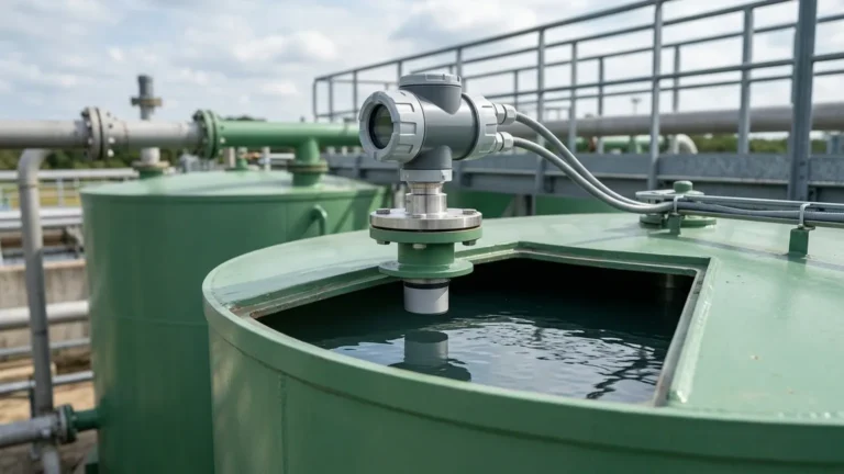
Ultrasonic Level Sensor with Display
Ultrasonic Level Sensor with Display: Engineering Selection and Application Guide
In modern industrial automation, the ability to monitor liquid and solid levels accurately without physical contact is a critical requirement. Among the various technologies available, Ultrasonic Level Meters have emerged as a versatile and cost-effective solution for a wide range of applications. Integrating a local display into these sensors significantly enhances their utility, providing real-time data at the point of measurement and simplifying the commissioning process. This guide explores the measurement principles, selection criteria, and practical installation considerations for an ultrasonic level sensor with display.
Understanding Ultrasonic Level Measurement Principles
Ultrasonic level measurement is based on the "Time of Flight" (ToF) principle. The sensor, typically mounted at the top of a tank or vessel, contains a piezoelectric transducer that emits high-frequency sound pulses. These sound waves travel through the air or gas space above the medium, reflect off the surface of the material, and return to the transducer.
The Calculation Logic
The distance between the sensor and the material surface is calculated using the formula:
D = (c × t) / 2
Where:
* D is the distance to the surface.
* c is the speed of sound in the medium (approximately 344 m/s in air at 20°C).
* t is the total time elapsed between the emission and reception of the pulse.
Since the height of the vessel (H) is known, the actual level (L) of the material is determined by subtracting the measured distance from the total height: L = H – D.
Temperature Compensation
The speed of sound is highly dependent on the temperature of the air through which it travels. A change of 1°C can result in a 0.17% error in distance measurement. To maintain accuracy, a professional ultrasonic level sensor with display includes a built-in temperature sensor to provide automatic compensation, ensuring reliable readings across varying environmental conditions.
The Role of Integrated Displays in Industrial Monitoring
While many sensors transmit data directly to a Programmable Logic Controller (PLC) or Distributed Control System (DCS), the inclusion of an integrated display offers several distinct advantages for plant engineers and maintenance teams.
1. Local Monitoring: Operators can verify the tank level immediately at the site without needing to check a central control room. This is particularly useful during manual filling operations or for remote tanks.
2. Simplified Configuration: An ultrasonic level sensor with display usually features a menu-driven interface with push-buttons or magnetic keys. This allows users to set parameters such as tank height, relay setpoints, and output scaling (4-20mA) directly on the device.
3. Real-Time Diagnostics: Modern displays provide more than just a level reading. They often show echo strength, signal quality, and error codes (such as "Lost Echo" or "Sensor Error"), which are invaluable for troubleshooting.
4. Visual Confirmation: Many displays include bar graphs or percentage indicators, providing a quick visual reference of the vessel's capacity.
Key Technical Specifications for Selection
When selecting an Ultrasonic Level Meters for a specific application, several technical parameters must be evaluated to ensure performance and longevity.
Measurement Range and Dead Zone
Every ultrasonic sensor has a "dead zone" (also known as the blocking distance) directly beneath the transducer. In this zone, the sensor cannot accurately measure the level because the transducer is still vibrating from the emission of the pulse when the reflection returns. Typical dead zones range from 0.25 meters to 0.6 meters (approx. 10 to 24 inches), depending on the maximum range of the sensor.
Beam Angle
The ultrasonic pulse spreads out in a cone shape. The beam angle (typically between 5° and 12°) determines the area the pulse covers. A narrower beam angle is preferable for tall, narrow tanks to avoid false reflections from internal obstructions like ladders, pipes, or agitators.
Output Signals and Communication
Standard industrial sensors provide a 4-20mA analog output. However, for integration into modern automation networks, options such as HART, RS485 (Modbus RTU), or Profibus are often required. The inclusion of programmable relays allows the sensor to act as a level switch for high/low alarms or pump control.
Practical Selection Table for Ultrasonic Level Meters
The following table provides a comparison of typical configurations for an ultrasonic level sensor with display based on common industrial requirements.
| Feature | Standard Liquid Application | Chemical/Corrosive Application | Long-Range/Solid Application |
| :— | :— | :— | :— |
| Measurement Range | 0.4m to 10m | 0.25m to 5m | 0.8m to 30m |
| Housing Material | ABS or Polycarbonate | PVDF or PTFE | Cast Aluminum or SS316 |
| Display Type | Backlit LCD | Backlit LCD | High-Contrast OLED/LCD |
| Accuracy | ±0.25% to ±0.5% of range | ±0.2% of range | ±0.5% of range |
| Protection Rating | IP65 / IP66 | IP67 / IP68 | IP67 / Explosion-proof |
| Typical Use Case | Water tanks, sumps | Acid storage, chemical dosing | Large silos, river levels |
Installation Guidelines and Best Practices
Correct installation is paramount to the accuracy of an ultrasonic level sensor with display. Even the most advanced sensor will fail if it is poorly positioned.
Positioning and Alignment
* Vertical Alignment: The sensor must be mounted perfectly perpendicular to the liquid surface. A tilt of even a few degrees can cause the reflected signal to miss the transducer, leading to a loss of signal.
* Wall Distance: Avoid mounting the sensor too close to the tank wall. The rule of thumb is to maintain a distance from the wall equal to at least 1/6th of the tank height to prevent interference from wall echoes.
* Inlet Interference: Never mount the sensor directly above the tank inlet. The turbulence and noise from the incoming liquid will disrupt the ultrasonic signal.
Obstruction Management
If internal obstructions like agitators or support beams cannot be avoided, many ultrasonic level meters offer "False Echo Suppression." This software feature allows the user to map out static reflections so the sensor ignores them and only tracks the moving surface of the material.
Mounting in Nozzles
If the sensor is mounted on a standpipe or nozzle, ensure the transducer face extends slightly below the bottom of the nozzle. If the transducer is recessed, the pulse may reflect off the inner edges of the nozzle, creating a massive dead zone and inaccurate readings.
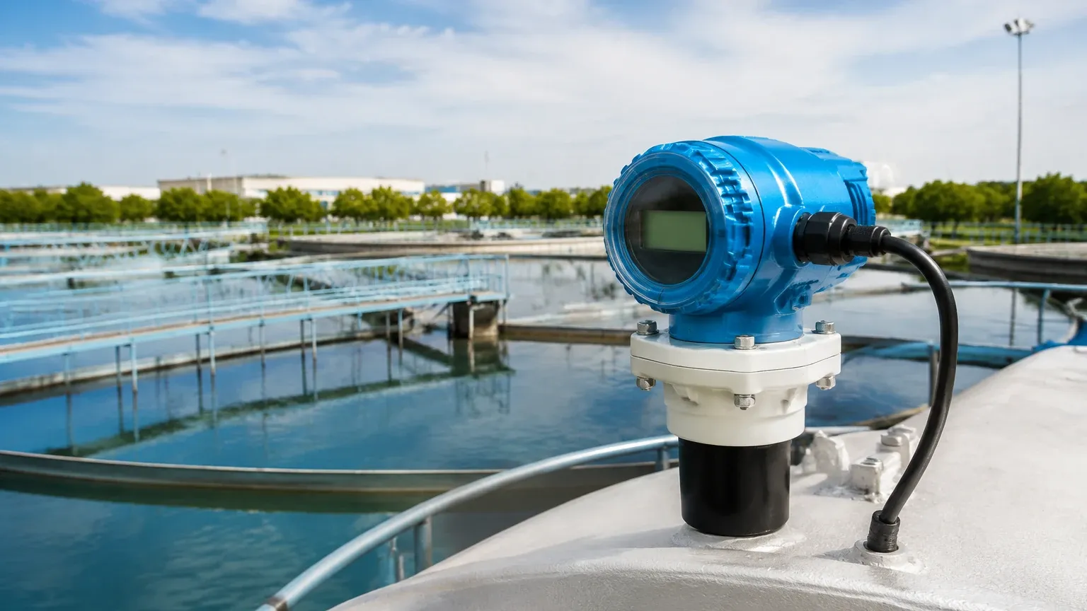
Environmental Limitations and Challenges
While ultrasonic technology is robust, it is not a "one-size-fits-all" solution. Engineers must be aware of the following limitations:
* Vacuum Conditions: Ultrasonic waves require a medium (air or gas) to travel. They cannot function in a vacuum.
* Heavy Foam: Thick, dense foam on the surface of a liquid can absorb the ultrasonic pulse rather than reflecting it, leading to inconsistent readings. In such cases, radar or hydrostatic sensors may be more appropriate.
* High Pressure and Temperature: Extreme pressures can change the density of the air, affecting the speed of sound beyond the capabilities of standard compensation. Similarly, temperatures exceeding 80°C (176°F) can damage the transducer or significantly degrade accuracy.
* Dust and Vapor: While light dust is usually fine, extremely heavy dust in grain silos or thick steam in boiling tanks can scatter the signal. For these environments, high-power transducers or specialized radar level meters are recommended.
Maintenance and Diagnostic Procedures
An ultrasonic level sensor with display is generally low-maintenance due to its non-contact nature. However, periodic checks ensure long-term reliability.
1. Transducer Cleaning: In applications with high humidity or splashing, condensation or residue can build up on the transducer face. Gently cleaning the face with a soft cloth and water can restore signal strength.
2. Echo Profile Analysis: Use the integrated display to view the echo strength. A declining signal strength over time may indicate environmental changes or the need for cleaning.
3. Cable Integrity: Ensure that cable glands are tight and that there is no moisture ingress into the housing, which could cause electronic failure or fogging of the display.
Frequently Asked Questions (FAQs)
Q: Can I use an ultrasonic level sensor for solids like sand or grain?
A: Yes, but with considerations. Solids do not reflect sound as efficiently as liquids and often have an angle of repose (a sloped surface). You should select a sensor with a higher power output and a wider range than the actual depth of the silo to account for signal attenuation.
Q: What is the difference between a 2-wire and 4-wire sensor?
A: A 2-wire sensor is loop-powered, meaning the same two wires provide power and carry the 4-20mA signal. These are easier to wire but have limited power for the display backlight and signal processing. A 4-wire sensor has separate wires for power (e.g., 24VDC or 220VAC) and signal, allowing for brighter displays and more powerful transducers.
Q: How does wind affect the measurement?
A: In outdoor applications, such as river level monitoring, strong winds can "blow" the ultrasonic pulse away from the vertical path, causing intermittent signal loss. Using a stilling well or a sensor with a higher pulse frequency can mitigate this effect.
Conclusion
The ultrasonic level sensor with display represents a vital tool for industrial process control, offering a balance of accuracy, ease of use, and cost-efficiency. By understanding the underlying physics and following rigorous installation standards, engineering teams can implement reliable level monitoring solutions across water treatment, chemical processing, and automation sectors. For projects requiring high-precision instrumentation and customized OEM/ODM services, selecting the right technology partner is essential to ensure the longevity and safety of the installation.