Ultrasonic Level Sensor Working Principle PDF
Ultrasonic Level Sensor Working Principle PDF
In the landscape of industrial automation, non-contact level measurement has become a standard for reliability and hygiene. Engineers and procurement specialists frequently search for an ultrasonic level sensor working principle pdf to serve as a foundational reference for system design and instrument selection. This guide provides a detailed technical breakdown of how these instruments function, their application boundaries, and the critical factors that influence their performance in real-world industrial environments.
As a professional manufacturer, Welk specializes in delivering high-accuracy Ultrasonic Level Meters that leverage these principles to provide cost-effective solutions across water treatment, chemical processing, and industrial automation sectors.
1. The Fundamental Physics of Ultrasonic Measurement
At its core, an ultrasonic level sensor is a distance-measuring device that utilizes sound waves—specifically frequencies above the range of human hearing (typically 20 kHz to 200 kHz). The measurement process is based on the "Time-of-Flight" (ToF) principle.
1.1 The Time-of-Flight (ToF) Principle
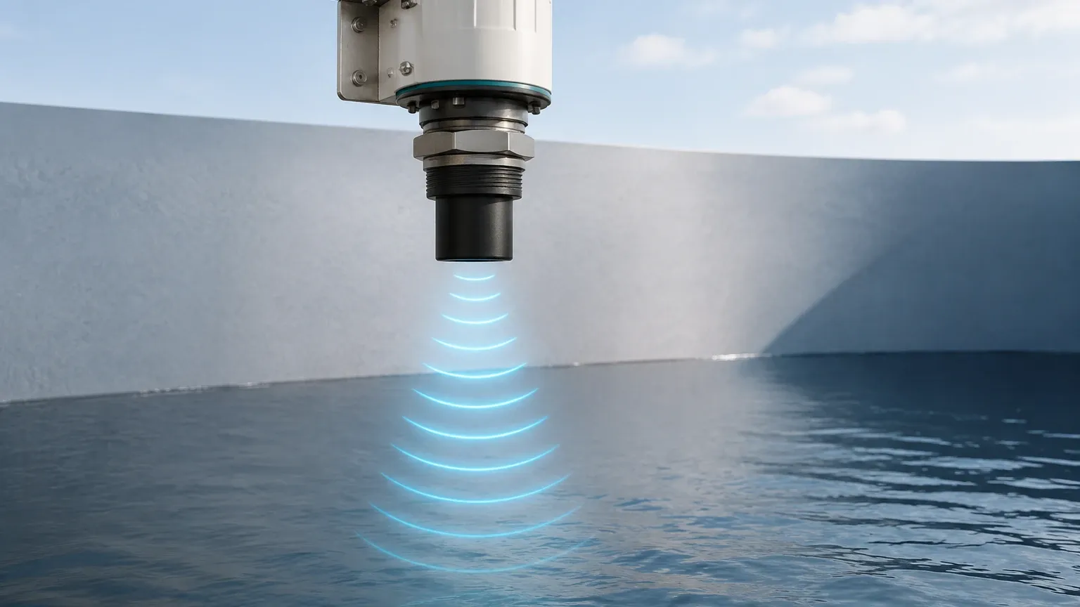
The sensor’s transducer acts as both a transmitter and a receiver. It emits a brief pulse of ultrasonic energy toward the target surface. When these waves hit the medium (liquid or solid), they are reflected back to the sensor. The onboard electronics then measure the time interval between the emission of the pulse and the reception of the echo.
The distance between the sensor and the material surface is calculated using the following formula:
D = (c × t) / 2
Where:
* D is the distance from the sensor to the material surface (meters).
* c is the speed of sound in the medium (approximately 344 m/s in air at 20°C).
* t is the total time elapsed for the pulse to travel to the surface and back (seconds).
Since the pulse travels to the surface and returns, the total distance is divided by two to find the distance to the target. The actual level of the material in a tank is then determined by subtracting this measured distance from the total tank height (the calibration distance).
1.2 The Role of the Piezoelectric Transducer
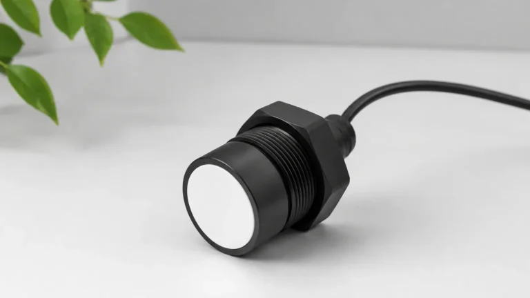
The heart of the instrument is the piezoelectric crystal. When an electrical signal is applied to the crystal, it vibrates at a high frequency, creating sound waves. Conversely, when the returning echo hits the crystal, it generates a small electrical voltage, which the sensor’s microprocessor interprets as the return signal.
2. Technical Components and Signal Processing
Modern industrial ultrasonic level meters are more than just simple pulse emitters. They incorporate sophisticated electronics to ensure accuracy in turbulent or noisy environments.
2.1 Signal Filtering and Echo Analysis
One of the primary challenges in ultrasonic measurement is distinguishing the true echo from the surface of the material from "false echoes" caused by tank obstructions (such as agitators, ladders, or internal piping). Advanced sensors use software algorithms to perform "False Echo Suppression." During commissioning, the sensor maps the internal profile of an empty tank, allowing the electronics to ignore static reflections and focus only on the moving level of the product.
2.2 Temperature Compensation
The speed of sound (c) is not a constant; it varies significantly with the temperature of the air or gas through which it travels. For instance, the speed of sound increases by approximately 0.6 m/s for every degree Celsius increase in temperature. To maintain accuracy, high-quality ultrasonic level meters include an integrated temperature sensor. The device automatically adjusts the distance calculation based on the ambient temperature near the transducer face.
3. Practical Selection Criteria for Industrial Applications
When reviewing an ultrasonic level sensor working principle pdf for procurement purposes, it is essential to match the sensor specifications to the specific process conditions. The following table provides a reference for common selection parameters.
Table 1: Ultrasonic Level Meter Selection Matrix
| Feature | Specification Range | Application Context |
| :— | :— | :— |
| Measurement Range | 0.1m to 30m | Short range for sumps; long range for large silos or reservoirs. |
| Beam Angle | 5° to 15° | Narrower beams are better for tall, narrow tanks with internal obstructions. |
| Output Signal | 4-20mA, RS485, HART | Integration with PLC, SCADA, or local display units. |
| Housing Material | ABS, PVC, PVDF, Stainless Steel | PVDF is required for corrosive chemical storage (acids/alkalis). |
| Operating Temp | -40°C to +70°C | Standard industrial range; requires shielding for extreme heat. |
| Accuracy | ±0.25% to ±0.5% of range | Sufficient for most process control and inventory management. |
4. Installation Guidelines and Best Practices
The reliability of an ultrasonic level sensor is heavily dependent on proper installation. Even the most advanced sensor will fail if the physical laws governing sound propagation are ignored.
4.1 The "Dead Zone" (Blocking Distance)
Every ultrasonic sensor has a "dead zone" immediately in front of the transducer face (typically 0.1m to 0.5m depending on the frequency). In this zone, the transducer is still vibrating from the emission and cannot yet "hear" a returning echo. The sensor must be mounted high enough so that the maximum liquid level never enters this dead zone.
4.2 Mounting Orientation
* Perpendicularity: The transducer face must be perfectly parallel to the liquid surface. If the sensor is tilted, the sound wave will reflect away from the sensor rather than back to it, resulting in signal loss.
* Avoid the Center: In round tanks, avoid mounting the sensor in the exact center, as this can cause multiple reflections to converge and create false readings.
* Inflow Interference: Never mount the sensor directly above the filling inlet. The falling liquid or solids will interfere with the ultrasonic pulse.
4.3 Beam Clearance
The ultrasonic pulse spreads out in a cone shape. The "beam angle" defines this spread. Ensure that no internal structures (pipes, reinforcement beams) enter this cone. If an obstruction is unavoidable, use a sensor with a narrower beam angle or utilize software-based echo masking.
5. Limitations and Application Boundaries
While ultrasonic technology is versatile, certain process conditions can attenuate or distort the sound signal, making other technologies (like radar) more suitable.
* Vacuum Conditions: Sound requires a medium to travel. Ultrasonic sensors cannot function in a vacuum.
* Heavy Foam: Thick, aerated foam on the surface of a liquid acts as a sound absorber. If the foam absorbs the pulse, no echo returns to the sensor.
* High Pressure/Extreme Temperature: High pressure changes the density of the air, affecting the speed of sound beyond what standard temperature compensation can handle. Extreme temperatures can also damage the piezoelectric element.
* Dust and Vapor: While light dust is manageable, extremely dense dust or heavy steam can scatter the ultrasonic signal. In these cases, high-frequency radar is often recommended.
6. Maintenance and Troubleshooting
Ultrasonic level meters are low-maintenance because they have no moving parts and do not contact the medium. However, periodic checks are recommended:
1. Transducer Face Cleaning: In applications with heavy condensation or chemical buildup, the transducer face should be wiped clean with a soft cloth to ensure clear pulse transmission.
2. Calibration Verification: Periodically verify the sensor reading against a manual tape measure to ensure the temperature compensation and electronics remain accurate.
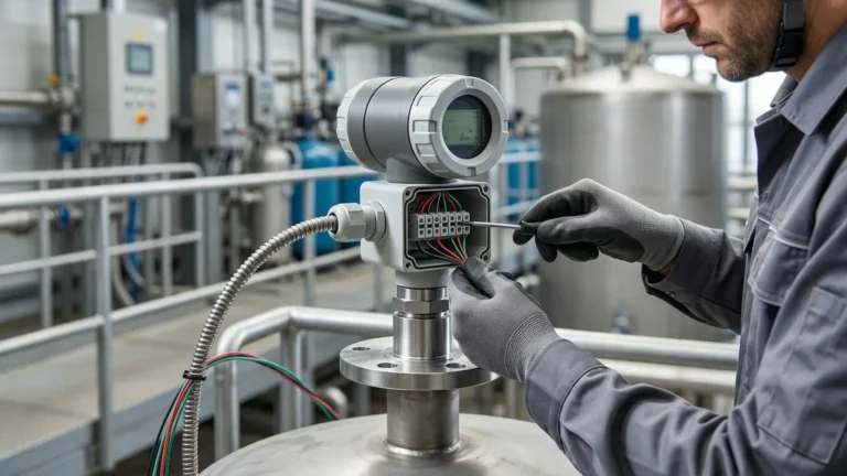
3. Cable Integrity: Ensure that cable glands are tight and that there is no moisture ingress into the electronics housing, especially in outdoor or wash-down environments.
7. Frequently Asked Questions (FAQ)
Q: Can ultrasonic sensors measure the level of solids?
A: Yes, but with limitations. Solids like grain or plastic pellets often have an irregular surface that scatters the sound wave. Usually, a sensor with a higher power output and a lower frequency is required for solids compared to liquids.
Q: How does wind affect outdoor ultrasonic level measurement?
A: Strong wind can "blow" the sound wave away or create turbulence in the air, leading to inconsistent readings. In open-air reservoirs, using a stilling well or a protective shroud can help stabilize measurements.
Q: What is the difference between a 2-wire and a 4-wire ultrasonic sensor?
A: A 2-wire sensor receives its power and transmits its 4-20mA signal over the same pair of wires, making it easier to install. A 4-wire sensor has separate wires for power and signal, which is often necessary for long-range sensors that require more power for the transducer.
Conclusion
Understanding the ultrasonic level sensor working principle pdf is the first step in optimizing process efficiency. By recognizing the relationship between sound velocity, temperature, and tank geometry, engineers can implement measurement systems that are both accurate and durable.
Welk continues to support global industries with robust Ultrasonic Level Meters designed for the rigors of modern industrial automation. Whether you are managing a municipal water facility or a complex chemical plant, selecting the right ultrasonic technology ensures long-term operational success and reduced maintenance costs.
Download Ultrasonic Level Sensor Working Principle PDF as a PDF