Ultrasonic Water Level Sensor 4 20ma
Understanding the Ultrasonic Water Level Sensor 4-20mA: A Comprehensive Engineering Guide
In the realm of industrial automation and fluid management, the ability to monitor liquid levels accurately and remotely is a fundamental requirement. Among the various technologies available, the ultrasonic water level sensor 4-20mA has emerged as a standard solution for non-contact measurement. By combining high-frequency acoustic waves with the industry-standard 4-20mA analog output, these devices provide a reliable bridge between physical tank levels and digital control systems like PLCs (Programmable Logic Controllers) or SCADA systems.
This guide explores the technical principles, selection criteria, and installation best practices for Ultrasonic Level Meters, focusing specifically on the integration of the 4-20mA current loop in water and wastewater applications.
1. Measurement Principles: How Ultrasonic Sensors Work
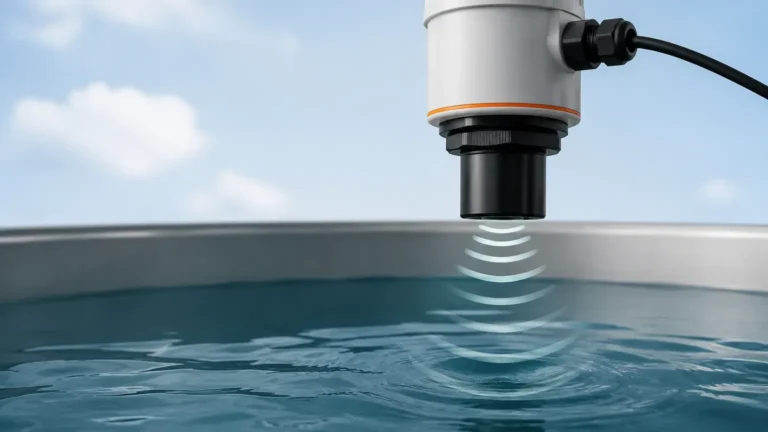
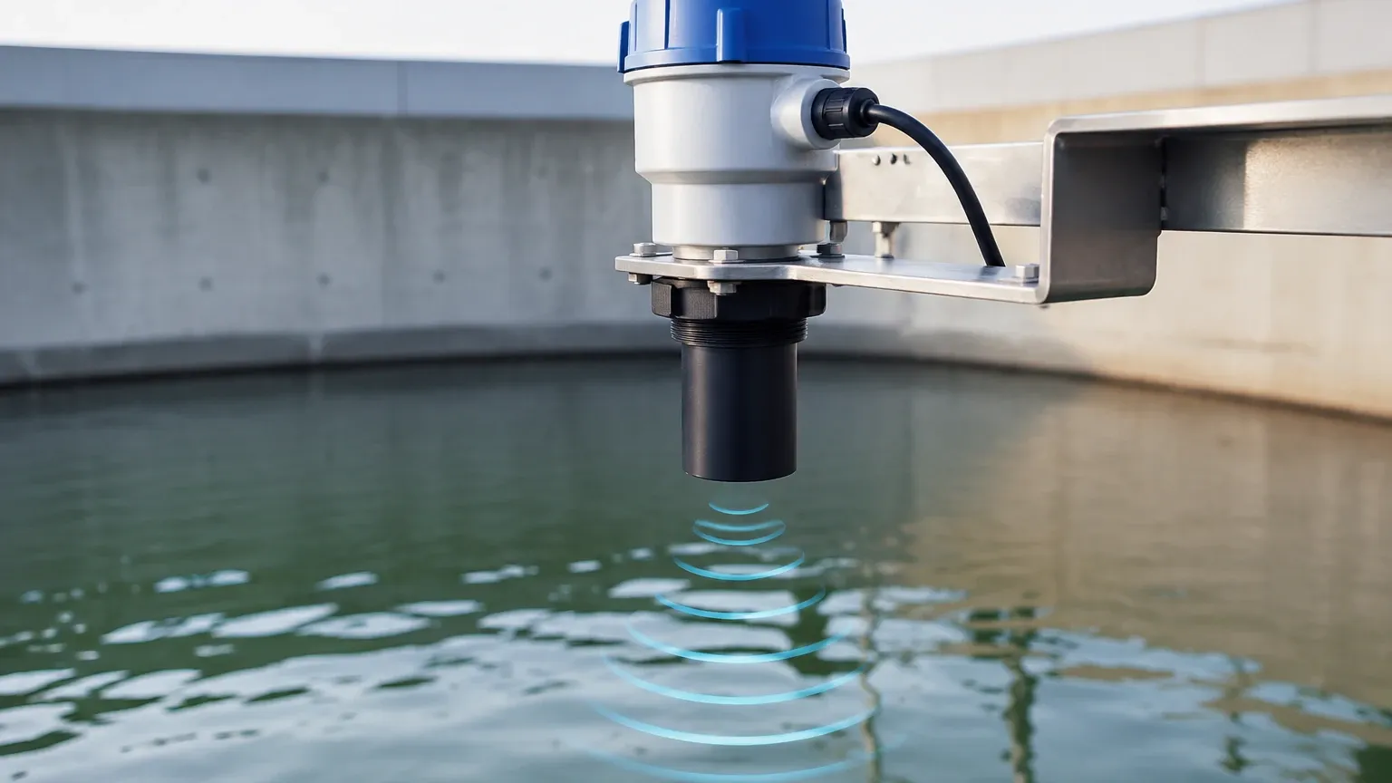
Ultrasonic level measurement is based on the "Time of Flight" (ToF) principle. The sensor, typically mounted at the top of a vessel or above a water channel, contains a piezoelectric transducer that performs two functions: emitting a high-frequency sound pulse and receiving the echo.
The Acoustic Cycle
1. Emission: The sensor transmits an ultrasonic pulse (typically between 20 kHz and 200 kHz) toward the liquid surface.
2. Reflection: The sound wave travels through the air, hits the surface of the water, and reflects back toward the sensor.
3. Detection: The transducer detects the returning echo.
4. Calculation: The internal microprocessor calculates the distance ($D$) based on the time delay ($t$) and the speed of sound in air ($v$), using the formula:
$$D = \frac{v \times t}{2}$$
To determine the actual liquid level ($L$), the device subtracts the measured distance from the total tank height ($H$): $L = H – D$.
Temperature Compensation
The speed of sound in air is not constant; it fluctuates with temperature (approximately 0.6 m/s per degree Celsius). Most professional-grade ultrasonic water level sensor 4-20mA units include an integrated temperature probe to automatically adjust the calculation, ensuring accuracy across varying environmental conditions.
2. The Significance of the 4-20mA Output
While ultrasonic sensors can offer digital outputs (such as RS485/Modbus), the 4-20mA analog current loop remains the most prevalent interface in industrial environments. This preference is due to several technical advantages:
* Noise Immunity: Unlike voltage signals (0-10V), current signals are highly resistant to electromagnetic interference (EMI) and voltage drops over long cable runs, which are common in large-scale water treatment plants.
* Live Zero: A 4mA signal represents the 0% level (empty), while 20mA represents 100% (full). If the signal drops to 0mA, the control system immediately identifies a fault, such as a broken wire or power loss, which would be indistinguishable from a "zero" reading in a 0-10V system.
* Loop Powering: Many sensors are "two-wire" devices, meaning the same pair of wires carries both the power to the sensor and the 4-20mA measurement signal back to the controller, simplifying wiring and reducing costs.
3. Practical Selection Criteria
Choosing the right ultrasonic water level sensor 4-20mA requires an evaluation of the specific application environment. Engineers must look beyond the basic range to ensure long-term reliability.
Key Evaluation Factors
| Feature | Description | Engineering Impact |
| :— | :— | :— |
| Measuring Range | The maximum distance the pulse can travel and return. | Standard ranges are 5m, 10m, and 15m. Over-specifying range can reduce resolution. |
| Blind Zone (Dead Zone) | The area directly below the transducer where measurement is impossible. | Typically 0.2m to 0.5m. The liquid must never enter this zone or the sensor will fail to read. |
| Beam Angle | The width of the ultrasonic cone (usually 5° to 12°). | Narrower beam angles are better for narrow tanks or vessels with internal obstructions. |
| Material Compatibility | The housing material (PP, PVDF, or PTFE). | PVDF is required for corrosive chemicals; PP is standard for water. |
| IP Rating | Ingress Protection against dust and water. | IP67 is minimum for outdoor use; IP68 is required if the sensor might be submerged. |
4. Installation Considerations and Best Practices
Correct installation is the single most important factor in the performance of Ultrasonic Level Meters. Even the most advanced sensor will provide erratic data if positioned poorly.
Positioning the Sensor
* Perpendicularity: The sensor face must be perfectly parallel to the liquid surface. A tilt of even a few degrees can cause the reflected signal to bounce away from the transducer, resulting in a "Loss of Echo" error.
* Avoid the Center: In cylindrical tanks, avoid mounting the sensor in the exact center. This can lead to multiple reflections (parabolic effect) that confuse the microprocessor.
* The Cone of Silence: Ensure there are no obstructions (ladders, pipes, agitators) within the ultrasonic beam's path. If the beam hits a fixed object, the sensor will report a constant, false level.
* Distance from Wall: The sensor should be mounted at a distance from the wall at least 1/6th of the tank height to prevent wall interference.
Mounting Methods
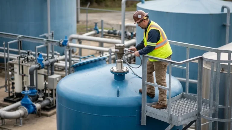
1. Flange Mounting: Common for enclosed tanks and chemical vessels.
2. Bracket Mounting: Used for open channels, sumps, or reservoirs.
3. Threaded Mounting: Standard for small tanks and integrated systems.
5. Limitations and Technical Challenges
While highly versatile, the ultrasonic water level sensor 4-20mA is not a universal solution. Certain physical conditions can impede the transmission of sound waves.
* Surface Foam: Heavy, thick foam absorbs ultrasonic pulses rather than reflecting them. In such cases, a radar level meter or a contact-based solution like a magnetic level gauge may be required.
* Vapor and Steam: High concentrations of steam or chemical vapors can change the density of the air, affecting the speed of sound beyond what standard temperature compensation can correct.
* Vacuum or High Pressure: Sound requires a medium to travel. Ultrasonic sensors cannot function in a vacuum. High pressure also alters the air density and sound velocity.
* Extreme Turbulence: Rapidly moving or boiling liquid creates an uneven surface that scatters the ultrasonic signal. Using a stilling well (a pipe inserted into the liquid) can help stabilize the surface for the sensor.
6. Applications in Industrial Automation
Water and Wastewater Treatment
In municipal water systems, these sensors are used to monitor reservoir levels, pump station wet wells, and open-channel flow in flumes and weirs. The 4-20mA signal allows for automated pump control, preventing dry-running or overflows.
Chemical Storage
For non-contact measurement of acids and bases, a PVDF-housed ultrasonic sensor provides a maintenance-free alternative to mechanical floats. Because the sensor never touches the liquid, there is no risk of corrosion or contamination.
Industrial Sumps and Reservoirs
Monitoring cooling water or runoff in factory sumps ensures environmental compliance. The 4-20mA output can be fed into a data logger to maintain records of water usage or discharge.
7. Frequently Asked Questions (FAQ)
Q: How do I calibrate the 4-20mA output?
A: Most modern sensors feature a built-in display and buttons or a digital interface. You set the "Zero" point (e.g., 4mA = 0 meters level) and the "Span" point (e.g., 20mA = 5 meters level). The sensor then scales the output linearly between these two points.
Q: What is the maximum cable length for a 4-20mA sensor?
A: Depending on the wire gauge and the power supply voltage, 4-20mA signals can typically travel up to 1,000 meters (approx. 3,280 feet) without significant signal degradation, provided shielded twisted-pair cabling is used to minimize interference.
Q: Can an ultrasonic sensor measure solids?
A: Yes, but with limitations. Solids like grain or sand do not have a flat surface; they form a cone. This scatters the signal, often requiring a sensor with a higher power output and a wider beam to capture a reliable average level.
Q: My sensor shows a full tank when it is actually empty. What is wrong?
A: This is often caused by the "Dead Zone" or a reflection from a nearby obstruction. If the water level reaches the sensor's face, it may lock onto the highest possible reading. Alternatively, an internal pipe or ladder might be reflecting the signal, which the sensor interprets as the liquid surface.
Conclusion
The ultrasonic water level sensor 4-20mA remains a cornerstone of industrial level monitoring due to its non-contact nature and ease of integration. By understanding the acoustic principles and adhering to strict installation guidelines, engineers can implement a robust measurement solution that reduces maintenance costs and improves process reliability. For complex applications involving foam or high pressure, consulting with a manufacturer to compare ultrasonic technology against radar or hydrostatic options is recommended to ensure the best fit for the operational environment.