3 Ultrasonic Flow Meter
3 Ultrasonic Flow Meter: A Professional Guide to Non-Contact Measurement
In modern industrial process control, the demand for non-invasive measurement has led to the widespread adoption of ultrasonic technology. Whether measuring the velocity of a liquid within a pipe or the volume of a liquid in a tank, ultrasonic instruments offer the distinct advantage of having no moving parts and no direct contact with the medium. For engineers specifying a 3 ultrasonic flow meter—typically referring to a 3-inch (DN80) nominal diameter instrument—or seeking to integrate Ultrasonic Level Meters into their flow monitoring systems, understanding the underlying physics and application constraints is essential for long-term reliability.
Understanding Ultrasonic Measurement Principles
Ultrasonic measurement relies on the propagation of high-frequency sound waves, usually above 20 kHz, through a medium. In industrial instrumentation, these waves are generated and received by piezoelectric transducers.
Transit-Time Principle (Flow)
For a 3 ultrasonic flow meter used in closed pipes, the most common method is the transit-time principle. This involves two transducers mounted on the pipe. One sends a signal upstream, and the other sends a signal downstream. Because the moving fluid carries the sound waves, the signal traveling downstream reaches its destination faster than the signal traveling upstream. The difference in time (Δt) is directly proportional to the flow velocity. Once the velocity is known, the meter calculates the volumetric flow rate based on the cross-sectional area of the 3-inch (80mm) pipe.
Time-of-Flight Principle (Level)
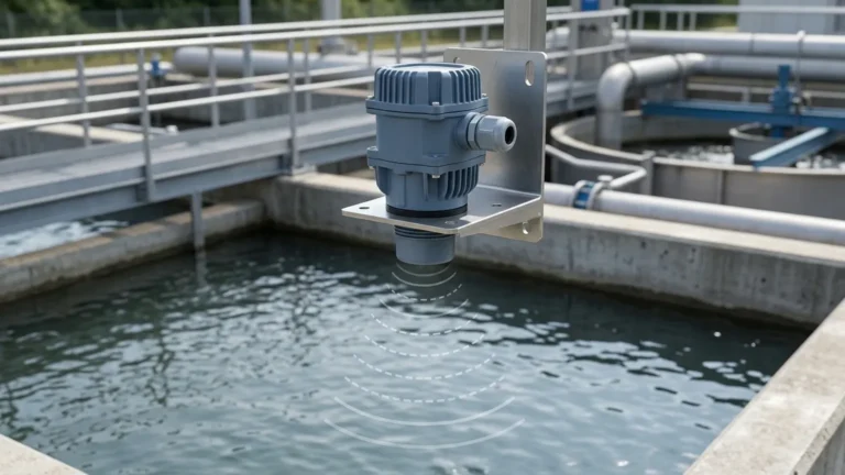
In contrast, ultrasonic level measurement uses a single transducer to emit a pulse toward a liquid surface. The pulse reflects off the surface and returns to the sensor. By measuring the total time of flight and knowing the speed of sound in air, the instrument calculates the distance to the surface. This is the primary mechanism used by Welk's range of level measurement solutions. In open-channel flow applications, an ultrasonic level meter is used to measure the "head" (height) of the liquid as it passes through a flume or weir, which is then converted into a flow rate using standard hydraulic equations.
The Role of the 3-Inch (DN80) Specification
The "3" in a 3 ultrasonic flow meter specification generally refers to the nominal pipe size (NPS 3 or DN80). This size is a standard in chemical processing, water distribution, and HVAC systems. Choosing an ultrasonic solution for this specific pipe size offers several advantages over mechanical meters:
1. Zero Pressure Drop: Unlike orifice plates or turbine meters, ultrasonic sensors do not obstruct the flow path, preventing energy loss.
2. Ease of Installation: For DN80 pipes, clamp-on ultrasonic flow meters can be installed without cutting the pipe or shutting down the process.
3. Maintenance: With no moving parts to wear out, these meters are ideal for corrosive or abrasive fluids that would damage mechanical components.
Technical Comparison: Flow vs. Level Measurement
When designing a system, it is important to distinguish between the requirements for pipe-based flow measurement and surface-based level measurement. The following table outlines the key differences for a standard 3-inch or equivalent industrial application.
| Feature | 3 Ultrasonic Flow Meter (Transit-Time) | Ultrasonic Level Meter (Level/Open Flow) |
| :— | :— | :— |
| Primary Metric | Velocity (m/s) | Distance/Height (m) |
| Installation | Inline or Clamp-on (DN80/3") | Top-mounted (Vertical) |
| Medium Requirement | Clean liquids (minimal bubbles/solids) | Reflective liquid or solid surface |
| Pipe/Channel | Full closed pipe | Open tank or Flume/Weir |
| Typical Accuracy | ±0.5% to ±2.0% of rate | ±0.25% to ±0.5% of range |
| Pressure Limits | Limited by pipe/flange rating | Typically atmospheric to 3 bar |
Selection Criteria for Industrial Applications
Selecting the correct instrument requires a detailed analysis of the process environment. For a 3 ultrasonic flow meter or a corresponding level sensor, consider the following factors:
Fluid Characteristics
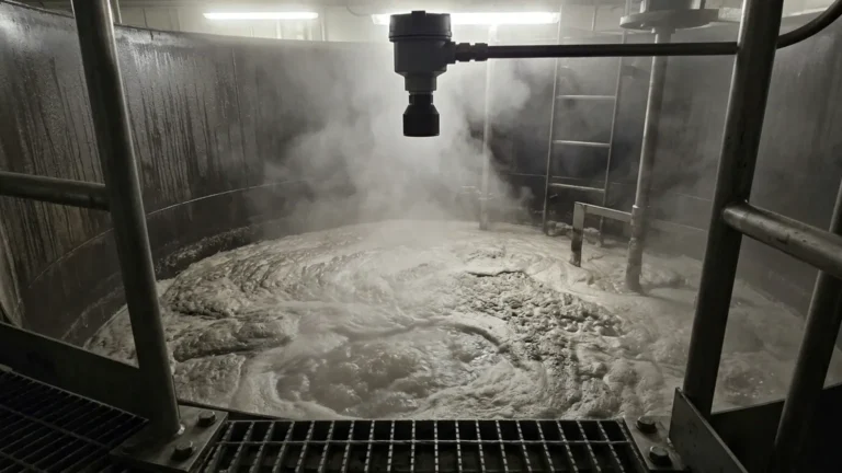
Ultrasonic waves are sensitive to the density and homogeneity of the medium. For transit-time flow meters, the liquid should be relatively clean. If the fluid contains more than 5% bubbles or suspended solids by volume, a Doppler-style meter may be required. For level measurement, the presence of heavy foam can absorb the ultrasonic signal, leading to "lost echo" errors.
Temperature and Speed of Sound
The speed of sound in air (for level) and in liquids (for flow) changes with temperature. For example, the speed of sound in air increases by approximately 0.6 m/s for every 1°C increase in temperature. High-quality Ultrasonic Level Meters include integrated temperature sensors to provide real-time compensation, ensuring accuracy across varying seasonal or process temperatures.
Pipe Material and Condition
For clamp-on 3-inch flow meters, the ultrasonic signal must pass through the pipe wall. Materials like carbon steel, stainless steel, and PVC are excellent conductors. However, internally lined pipes (e.g., cement or rubber lining) can attenuate the signal. It is critical to confirm the pipe wall thickness and lining material before selecting a clamp-on meter.
Installation Considerations and Best Practices
Proper installation is the single most important factor in ensuring the accuracy of ultrasonic instruments.
Straight Pipe Runs (Flow)
To achieve a stable flow profile in a 3-inch pipe, a 3 ultrasonic flow meter typically requires a minimum of 10 diameters (10D = 800mm) of straight pipe upstream and 5 diameters (5D = 400mm) downstream from the sensor. Obstructions like elbows, valves, or pumps create turbulence that can interfere with the ultrasonic signal.
Mounting and Dead Band (Level)
When installing level meters, the sensor must be mounted perpendicular to the liquid surface. Every ultrasonic level sensor has a "dead band" (or blocking distance), which is the zone immediately below the transducer face where it cannot measure. For a standard industrial sensor, this might be 0.25m to 0.5m (approx. 10 to 20 inches). The sensor must be positioned high enough so that the maximum liquid level never enters this dead band.
Electrical Configuration
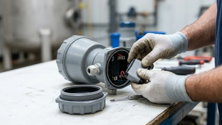
Many industrial sensors are available in 2-wire (loop-powered) or 3-wire configurations. A 3-wire setup often provides more power to the transducer, allowing for a stronger signal in challenging environments where dust or steam might be present. When searching for a 3 ultrasonic flow meter, verify if the "3" refers to the pipe size or a 3-wire electrical requirement for your PLC/SCADA integration.
Limitations and Common Risks
While highly versatile, ultrasonic technology is not a universal solution. Engineers should be aware of the following limitations:
* Vacuum Conditions: Ultrasonic waves cannot travel through a vacuum. Therefore, level meters cannot function in vacuum-sealed tanks.
* Vapor and Steam: Heavy steam or high concentrations of chemical vapors can alter the speed of sound or attenuate the signal, leading to measurement inaccuracies.
* Surface Turbulence: In level measurement, extreme agitation or vortexing can scatter the ultrasonic pulse. In such cases, a stilling well or a different technology, such as a radar level meter, may be more appropriate.
* Acoustic Short-Circuiting: In flow measurement, if the transducers are not properly coupled to the pipe (using ultrasonic grease or pads), the signal may travel through the pipe wall rather than the fluid, resulting in false readings.
Frequently Asked Questions (FAQ)
Q: Can a 3 ultrasonic flow meter measure gas flow?
A: Standard transit-time flow meters are designed for liquids. Gas flow measurement requires specialized high-power ultrasonic transducers due to the low density of gases and the high attenuation of sound waves.
Q: How do I handle measurement in a 3-inch pipe that is not always full?
A: Transit-time flow meters require a full pipe to function correctly. If the pipe is partially full, the meter will provide erratic readings. In these scenarios, an open-channel flow configuration using an ultrasonic level meter and a flume is the recommended engineering approach.
Q: What maintenance is required for these sensors?
A: Since there is no contact with the fluid, maintenance is minimal. For level meters, periodically check the transducer face for condensation or dust buildup. For clamp-on flow meters, ensure the acoustic coupling gel has not dried out over several years of service.
Q: Is ultrasonic technology suitable for high-pressure applications?
A: For level measurement, pressure is generally limited by the housing of the sensor (typically up to 3 bar). For flow measurement, clamp-on sensors are unaffected by internal pressure since they reside outside the pipe, making them ideal for high-pressure 3-inch lines where invasive tapping would be dangerous or expensive.
Conclusion
Whether you are implementing a 3 ultrasonic flow meter for precise liquid velocity monitoring or utilizing Ultrasonic Level Meters for tank inventory and open-channel flow, the success of the application depends on matching the technology to the environmental conditions. By accounting for fluid properties, pipe geometry, and potential signal interference, operators can achieve a high-accuracy, low-maintenance measurement solution that stands the test of time in demanding industrial landscapes.