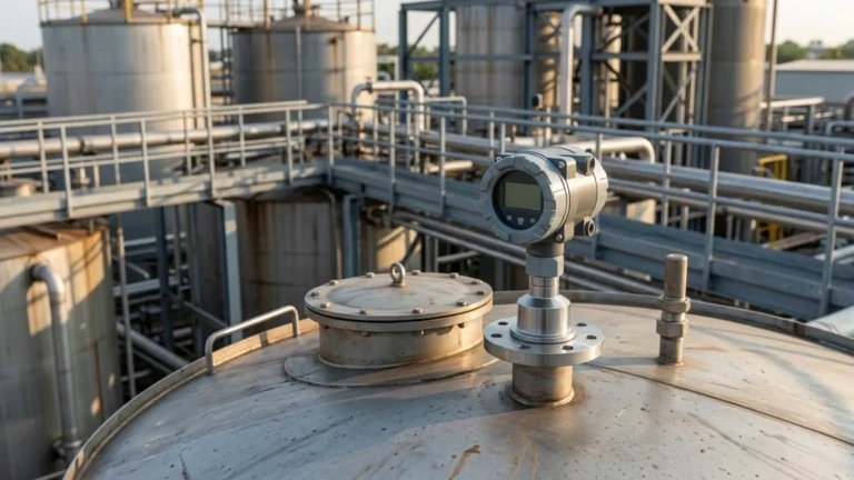
Vetus Ultrasonic Level Sensor Manual
Vetus Ultrasonic Level Sensor Manual: A Comprehensive Engineering Guide to Installation and Calibration
In the field of fluid management, non-contact level measurement has become the preferred standard for reliability and hygiene. Whether managing fuel tanks in a marine environment or monitoring chemical reagents in an industrial facility, understanding the documentation and operational parameters of your equipment is critical. The vetus ultrasonic level sensor manual serves as the primary technical reference for one of the most common sensors used in small-to-medium tank applications.
However, for engineers and procurement specialists, the manual is more than just a setup guide; it is a blueprint for ensuring system longevity and accuracy. This article explores the technical nuances found in the Vetus documentation, explains the core physics of Ultrasonic Level Meters, and provides a comparative framework for selecting the right instrumentation for various industrial environments.
1. Understanding the Principle of Ultrasonic Level Measurement
Before diving into the specifics of the *vetus ultrasonic level sensor manual*, it is essential to understand the physics that govern these devices. Ultrasonic sensors operate on the "Time of Flight" (ToF) principle.
The Measurement Cycle
1. Emission: The sensor's transducer emits a high-frequency sound pulse (typically between 40 kHz and 200 kHz).
2. Reflection: This sound wave travels through the air gap in the tank and hits the surface of the liquid or solid material.
3. Reception: The pulse reflects back to the transducer, which now acts as a receiver.
4. Calculation: The internal processor measures the time elapsed between emission and reception. Using the speed of sound in air (approximately 343 m/s or 1,125 ft/s at 20°C), the device calculates the distance to the surface.
The Importance of Temperature Compensation
The speed of sound is not constant; it fluctuates with air temperature. Most professional-grade Ultrasonic Level Meters include an integrated temperature sensor to adjust the calculation in real-time. Without this compensation, a 10°C shift in temperature could result in a measurement error of approximately 1.7%.
2. Key Technical Specifications in the Vetus Manual
The *vetus ultrasonic level sensor manual* outlines specific parameters that define the sensor's operational envelope. Unlike industrial radar or hydrostatic sensors, these ultrasonic units are often designed for specific tank depths and output protocols.
Signal Output and Compatibility
Vetus sensors are widely recognized for their compatibility with standard marine and industrial gauges. They typically offer two primary resistance-based outputs:
* European Standard: 0–190 Ohm (0 Ohm = Empty, 190 Ohm = Full).
* American Standard: 240–33 Ohm (240 Ohm = Empty, 33 Ohm = Full).
Modern digital versions may also support NMEA 2000 protocols for integration into networked bridge systems or PLC (Programmable Logic Controller) environments.
The "Dead Zone" (Blocking Distance)
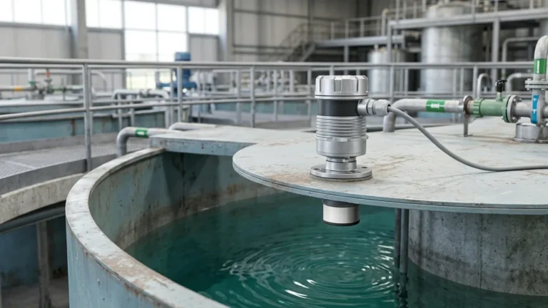
A critical detail in any ultrasonic manual is the "Dead Zone." This is the area immediately below the transducer where the sensor cannot accurately process a return signal because the transducer is still vibrating from the initial emission. For most Vetus models, this zone is approximately 100 mm to 200 mm (4 to 8 inches). If the liquid level enters this zone, the sensor will provide erratic readings or a "Full" error code.
3. Installation Best Practices and Geometric Considerations
Proper installation is the single most important factor in the performance of an ultrasonic sensor. The manual provides several non-negotiable guidelines to prevent signal interference.
Mounting Position
* Perpendicularity: The sensor must be mounted perfectly perpendicular to the liquid surface. A tilt of even 2 or 3 degrees can cause the sound pulse to reflect away from the transducer, resulting in a "Lost Echo" error.
* Distance from Walls: To avoid "false echoes" from tank walls or internal baffles, the sensor should be mounted at least 100 mm (4 inches) away from the side of the tank. A general rule of thumb is to keep the sensor away from the wall by at least 1/6th of the total tank height.
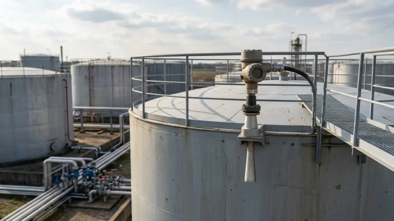
* Obstruction Clearance: Ensure that the "beam angle" (usually between 8° and 12°) is clear of ladders, pipes, or agitators. If an obstruction is unavoidable, many advanced Ultrasonic Level Meters allow for "False Echo Suppression," where the software is programmed to ignore reflections at a specific distance.
Selection Table: Ultrasonic vs. Other Technologies
| Feature | Ultrasonic Level Meters | Radar (ToF) | Hydrostatic Pressure | Magnetic Level Gauges |
| :— | :— | :— | :— | :— |
| Contact Type | Non-contact | Non-contact | Contact (Submerged) | Contact (External/Internal) |
| Accuracy | ±0.25% to ±0.5% | ±1 mm to ±5 mm | ±0.1% to ±0.5% | ±5 mm to ±10 mm |
| Ideal For | Water, Diesel, Wastewater | Acids, High Temp, Vacuum | Deep Wells, Vented Tanks | High-Pressure Boilers |
| Limitation | Foam, Dust, Vacuum | High Cost | Density Dependent | Moving Parts |
4. Calibration and Configuration Steps
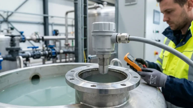
According to the *vetus ultrasonic level sensor manual*, calibration is necessary to map the sensor's range to the specific dimensions of your tank. This process usually involves setting the "Empty" and "Full" points.
1. Determine Tank Depth: Measure the distance from the sensor face to the bottom of the tank (the "Zero" point).
2. Set the Span: Determine the maximum height the liquid will reach (the "Full" point). Ensure this point remains below the Dead Zone.
3. Programming: Depending on the model, this is done via a digital interface, a series of DIP switches, or by using a calibration magnet. For NMEA 2000 models, configuration is often handled through a connected multi-function display (MFD).
5. Limitations and Environmental Factors
While ultrasonic technology is versatile, it is not a universal solution. Engineers must be aware of environmental conditions that can attenuate or distort the acoustic signal.
* Surface Foam: Heavy foam acts as an acoustic absorber. The sound pulse enters the foam and is scattered rather than reflected. In tanks with heavy agitation or foaming chemicals, radar or hydrostatic sensors are preferred.
* Vapor and Turbulence: High concentrations of volatile vapors (like gasoline) can change the density of the air, affecting the speed of sound. Similarly, extreme surface turbulence can scatter the signal.
* Vacuum/Pressure: Ultrasonic waves require a medium (air/gas) to travel. They cannot function in a vacuum. High-pressure environments also significantly alter the acoustic properties of the gas, leading to inaccuracies.

6. Troubleshooting Common Issues
When a sensor fails to provide a reading, the *vetus ultrasonic level sensor manual* suggests a systematic approach to troubleshooting:
* Symptom: Reading stays at "Full" regardless of level.
* *Cause*: The sensor is likely seeing a reflection from an obstruction within the dead zone or a build-up of condensation/debris on the transducer face.
* *Solution*: Clean the transducer face with a soft cloth and check for obstructions.
* Symptom: Erratic or jumping readings.
* *Cause*: This is often caused by surface turbulence or the sensor not being mounted perpendicular to the liquid.
* *Solution*: Increase the "Damping" or "Averaging" setting in the software, or install a stilling well to stabilize the surface around the sensor.
* Symptom: No Signal / Open Circuit.
* *Cause*: Wiring fault or incorrect resistance standard (matching a 0-190 Ohm sensor to a 240-33 Ohm gauge).
* *Solution*: Verify wiring continuity and check that the gauge and sensor share the same resistance standard.
7. Selecting the Right Instrument for Your Application
Choosing between a standard Vetus unit and industrial-grade Ultrasonic Level Meters depends on the complexity of the environment. Vetus sensors are excellent for standard-shaped tanks containing water or fuel in relatively stable conditions.
However, for industrial automation, chemical processing, or large-scale water treatment, Welk provides advanced solutions that offer:
* Higher Ingress Protection (IP68): For total submersion protection.
* Explosion-Proof Ratings (Ex d / Ex ia): Essential for hazardous zones.
* Advanced Signal Processing: To filter out noise from agitators and complex tank geometries.
* Multiple Output Options: Including 4-20mA, RS485 Modbus, and HART protocols.
Frequently Asked Questions (FAQ)
Q: Can I use the Vetus ultrasonic sensor for black water (sewage) tanks?
A: Yes. Because the sensor is non-contact, it is ideal for black water tanks as it prevents the fouling and corrosion issues common with float-style sensors. However, ensure the manual's instructions regarding the dead zone are followed to prevent the sensor from touching the waste.
Q: How do I shorten the cable on my ultrasonic sensor?
A: Most manuals state that cables can be shortened, but it is vital to use high-quality waterproof connectors or solder with heat-shrink tubing to maintain signal integrity, especially in marine environments.
Q: Does the sensor work in plastic tanks?
A: Yes, ultrasonic sensors work perfectly in plastic (polyethylene/GRP) tanks. Unlike some radar sensors that can "see through" plastic, ultrasonic waves reflect off any liquid surface regardless of the tank material.
Q: What is the maximum range of these sensors?
A: Standard Vetus units are typically optimized for depths up to 1.2 meters (4 feet) or 2 meters (6.5 feet). For deeper tanks or silos, industrial Ultrasonic Level Meters can reach distances of up to 30 meters (98 feet).
Conclusion
The *vetus ultrasonic level sensor manual* provides the foundational knowledge required for successful basic installations. By adhering to the mounting geometries, understanding the dead zone, and ensuring correct electrical integration, users can achieve reliable, maintenance-free level monitoring. For applications that exceed the capabilities of standard consumer-grade sensors—such as those involving corrosive chemicals, extreme heights, or integrated industrial automation—consulting with a professional manufacturer like Welk ensures that your level measurement solution is both accurate and cost-effective.