Z Wave Ultrasonic Sensor
Z Wave Ultrasonic Sensor: A Technical Guide to Wireless Level Monitoring
In the landscape of industrial automation and smart fluid management, the ability to monitor levels without physical contact is a significant advantage. Among the various technologies available, ultrasonic measurement remains a primary choice due to its reliability and cost-effectiveness. The emergence of the z wave ultrasonic sensor represents a convergence of proven acoustic sensing technology with modern wireless mesh networking, offering a versatile solution for both light industrial and commercial applications.
This guide explores the engineering principles behind ultrasonic level measurement, the specific implementation of Z-Wave protocols in sensing, and the critical factors engineers must consider when selecting and installing these instruments.
Understanding Ultrasonic Level Measurement Principles
Before evaluating specific wireless protocols like Z-Wave, it is essential to understand the physics of ultrasonic level measurement. These instruments operate on the "Time-of-Flight" (ToF) principle.
The Transducer Mechanism
An ultrasonic sensor contains a piezoelectric crystal that acts as both a transmitter and a receiver. When energized, the crystal vibrates at a specific frequency—typically between 20 kHz and 200 kHz—emitting a pulse of sound waves toward the target surface. These waves travel through the air, bounce off the surface of the medium (liquid or solid), and return to the sensor.
Distance Calculation
The sensor's internal processor measures the time interval between the emission of the pulse and the reception of the echo. The distance is calculated using the formula:
D = (c × t) / 2
Where:
* D is the distance to the surface.
* c is the speed of sound in the medium (air).
* t is the elapsed time.
Because the speed of sound is influenced by air temperature (approximately 0.6 m/s per degree Celsius), professional-grade Ultrasonic Level Meters incorporate integrated temperature sensors to provide real-time compensation, ensuring accuracy remains within ±0.25% of the detected range.
The Role of the Z Wave Ultrasonic Sensor in Automation
Z-Wave is a wireless communications protocol designed primarily for automation and sensor networks. Unlike Wi-Fi, which can be power-hungry and prone to interference in crowded industrial environments, Z-Wave operates on a sub-GHz band (908.42 MHz in the US, 868.42 MHz in Europe). This allows for better penetration through walls and less interference from 2.4 GHz devices.
Mesh Networking Capabilities
A z wave ultrasonic sensor functions as part of a mesh network. In this configuration, each mains-powered device acts as a repeater, passing the signal along until it reaches the central gateway. This is particularly useful in large facilities where a single sensor might be out of direct range of the primary controller. For battery-operated ultrasonic sensors, Z-Wave’s low-power consumption allows for multi-year operation on a single power source, depending on the reporting frequency.
Application Context
While Z-Wave sensors are frequently used in smart building management—such as monitoring heating oil tanks, sump pits, or water cisterns—they serve as an entry point for engineers looking to integrate level data into broader SCADA or building automation systems without the high cost of trenching and cabling.
Key Selection Criteria for Ultrasonic Level Meters
Selecting the right sensor requires an analysis of the process environment and the physical properties of the material being measured. Whether you are deploying a Z-Wave enabled device or a standard industrial transmitter, the following criteria apply:
1. Measurement Range and Dead Zone
Every ultrasonic sensor has a "Dead Zone" (also known as the blocking distance) directly in front of the transducer face. In this zone, the sensor cannot accurately process the returning echo because the crystal is still vibrating from the transmission. Typical dead zones range from 10 cm to 50 cm. If the liquid level rises into this zone, the sensor will provide false readings.
2. Beam Angle
The ultrasonic pulse is not a laser; it spreads out in a cone shape. The beam angle (usually between 5° and 12°) determines the footprint of the signal at a given distance. Engineers must ensure that the beam does not hit side walls, pipes, or agitators, as these obstructions will create "parasitic echoes" that interfere with the true level reading.
3. Material Compatibility
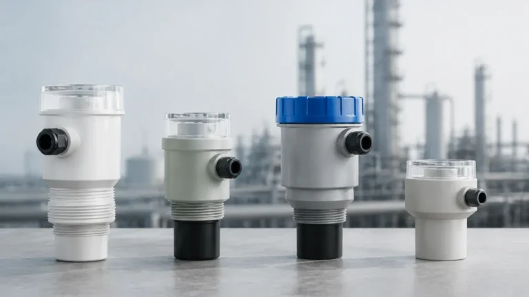
The housing of the sensor must withstand the atmosphere of the tank. For water and general use, Polypropylene (PP) is standard. For corrosive chemicals or acids, Polyvinylidene Fluoride (PVDF) is required to prevent degradation of the transducer face.
Installation Best Practices and Geometric Considerations
Proper installation is the single most important factor in the performance of an ultrasonic system. Follow these technical guidelines to ensure signal integrity:
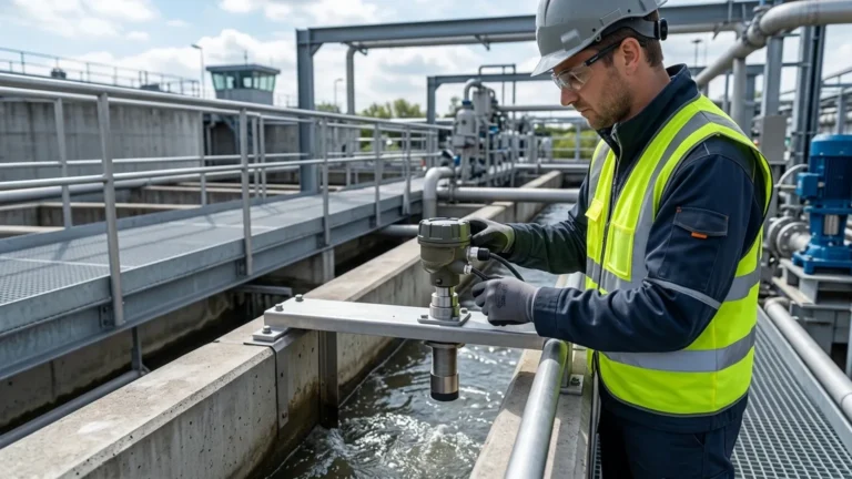
* Perpendicular Mounting: The sensor face must be mounted perfectly parallel to the liquid surface. A tilt of even a few degrees can cause the echo to bounce away from the receiver, leading to signal loss.
* Avoid the Center: In cylindrical tanks, do not mount the sensor in the exact center, as this can create a focal point for secondary echoes that confuse the processor.
* Distance from Walls: Always mount the sensor at least 20 cm to 30 cm away from the tank wall to prevent interference from the wall's surface roughness.
* Nozzle Geometry: If the sensor is mounted on a standpipe or nozzle, the inner diameter of the pipe must be smooth and the sensor face should extend slightly past the bottom of the nozzle to prevent internal reflections.

Environmental Limitations and Signal Interference
While highly versatile, ultrasonic technology has physical limitations that may necessitate alternative technologies like radar or hydrostatic pressure sensors.
1. Foam and Turbulence
Surface foam acts as an acoustic insulator, absorbing the ultrasonic pulse rather than reflecting it. If heavy foam is present, the sensor may report a "Lost Echo" error. Similarly, extreme turbulence can scatter the signal.
2. Vacuum and Pressure
Ultrasonic waves require a medium (air or gas) to travel. They cannot function in a vacuum. Furthermore, high-pressure environments change the density of the air, significantly altering the speed of sound and requiring complex compensation that exceeds the capabilities of standard sensors.
3. Dust and Vapors
Heavy dust in grain silos can attenuate the signal. Likewise, heavy vapors (such as those from gasoline or solvents) can change the acoustic impedance of the air space, leading to measurement errors if the sensor is not calibrated for that specific gas mixture.
Comparison Table: Selecting the Right Level Technology
The following table compares the z wave ultrasonic sensor against standard industrial ultrasonic and radar alternatives.
| Feature | Z-Wave Ultrasonic | Industrial Ultrasonic | Radar (60GHz/80GHz) |
| :— | :— | :— | :— |
| Primary Use | Residential/Light Commercial | Industrial Process Control | Critical/High-Precision |
| Connectivity | Wireless Mesh (Z-Wave) | 4-20mA, Modbus, HART | 4-20mA, Profibus, Bluetooth |
| Power Source | Battery or DC Plug | Loop-powered (2-wire) | Loop-powered or DC |
| Accuracy | ±1% to ±2% | ±0.25% | ±1mm to ±3mm |
| Max Range | Up to 4 meters | Up to 15-30 meters | Up to 120 meters |
| Installation | Non-invasive / Easy | Flange or Threaded | Flange or Threaded |
| Cost | Low | Moderate | High |
Frequently Asked Questions (FAQ)
Can a Z-Wave ultrasonic sensor be used for chemical tanks?
Yes, provided the transducer face is made of a chemically resistant material like PVDF. However, you must also ensure the Z-Wave gateway is located within a range that can penetrate the tank's enclosure, especially if the tank is metal.
How does temperature affect the accuracy of the sensor?
The speed of sound changes by approximately 0.17% per degree Celsius. Without temperature compensation, a 20°C shift could result in a 3.4% error. Most professional Ultrasonic Level Meters include an internal thermistor to automatically correct this.
What happens if the sensor loses its Z-Wave connection?
Most Z-Wave sensors will attempt to re-establish a connection automatically. However, for critical industrial applications, it is recommended to use sensors with local data logging or a secondary fail-safe output (like a dry contact relay) to prevent tank overflows during a network outage.
Is the Z-Wave frequency safe for industrial environments?
Yes, Z-Wave operates in the sub-GHz range, which is generally less congested than the 2.4 GHz band used by Wi-Fi and Bluetooth. It is highly resistant to interference from industrial machinery, though the data throughput is lower, making it ideal for periodic level updates rather than high-speed continuous control.
Can I measure solids with an ultrasonic sensor?
Yes, but with caveats. Solids like grain or sand do not form a flat surface; they form a cone (angle of repose). This scatters the ultrasonic signal. When measuring solids, it is often necessary to use a sensor with a higher power output and a lower frequency to ensure a return echo is detected.
For engineers and facility managers, the z wave ultrasonic sensor offers a cost-effective path to digitizing level data. By understanding the acoustic principles and environmental constraints detailed above, users can implement reliable monitoring solutions that improve operational efficiency and prevent costly spills or stockouts.