Sensor Io Link
Sensor Io Link
In the landscape of Industrial Internet of Things (IIoT) and Industry 4.0, the integration of smart communication protocols has become a cornerstone for operational efficiency. Among these, IO-Link (standardized under IEC 61131-9) stands out as a powerful, point-to-point communication technology used to connect sensors and actuators to a control system. For professionals managing industrial level measurement, understanding the nuances of a sensor IO-Link setup is essential for transitioning from traditional analog monitoring to digitized, data-driven process control.
At its core, IO-Link is not a fieldbus but a short-distance, bi-directional digital communication interface. It allows for the seamless exchange of process data, service data, and diagnostic information between a master and a device. In the context of level measurement, this means a radar or ultrasonic sensor can provide more than just a 4-20mA signal; it can report internal temperature, signal quality, and device status while allowing for remote parameterization.
Measurement Principles and IO-Link Integration
Before selecting a specific communication protocol, it is vital to understand the underlying measurement principles of the sensors being integrated. Level measurement instruments typically fall into non-contact or contact categories, each interfacing differently with an IO-Link master.
Radar Level Measurement
Radar level meters utilize high-frequency electromagnetic waves (often in the 26GHz or 80GHz range). The sensor emits a pulse that reflects off the medium's surface and returns to the receiver. The time-of-flight is calculated to determine the distance. When equipped with IO-Link, the radar sensor transmits this distance as digital process data. This eliminates the digital-to-analog conversion errors common in traditional systems, ensuring that the precision of the radar (often within ±2 mm) is preserved all the way to the PLC.
Ultrasonic Level Measurement
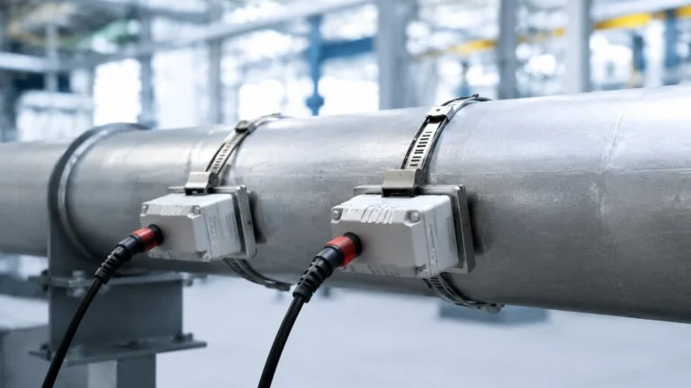
Ultrasonic sensors function by emitting sound waves that bounce off the liquid or solid surface. These are ideal for water treatment and simple chemical storage. An ultrasonic sensor with IO-Link can provide real-time feedback on the echo strength. If foam or turbulence begins to interfere with the sound waves, the sensor can trigger a diagnostic event via the IO-Link interface, allowing operators to intervene before a signal loss occurs.
Hydrostatic Level Measurement
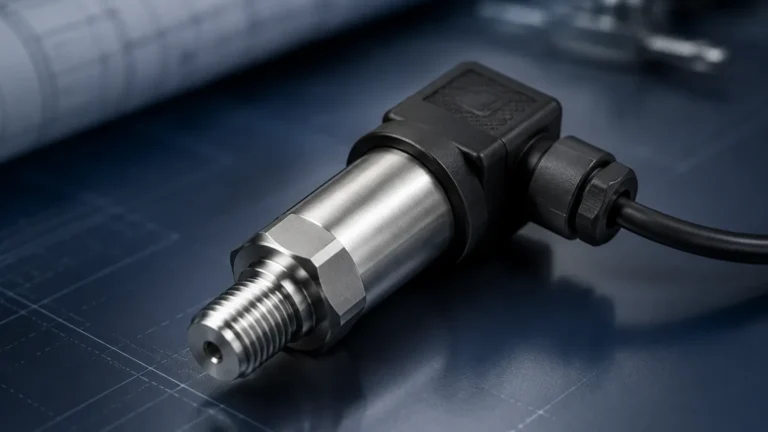
Hydrostatic transmitters measure the pressure exerted by a liquid column. This pressure is proportional to the height of the liquid and its density. In an IO-Link configuration, the hydrostatic sensor can transmit both the pressure value and the calculated level. Furthermore, integrated temperature sensors within the probe can provide secondary process data over the same three-wire cable, reducing the need for additional hardware.
The Architecture of an IO-Link System
An IO-Link system consists of three primary components: the IO-Link master, the IO-Link device (the sensor), and the unshielded three-wire cable connecting them.
1. The IO-Link Master: This acts as the gateway between the field devices and the higher-level fieldbus (such as PROFINET, EtherNet/IP, or Modbus TCP). A single master typically features 4 to 8 ports, each supporting one sensor.
2. The IO-Link Device: In this context, the level sensor. Each device is accompanied by an IODD (IO Device Description) file, which contains the device's identity, parameters, and communication properties. This file is loaded into the engineering tool to allow the PLC to "understand" the sensor.
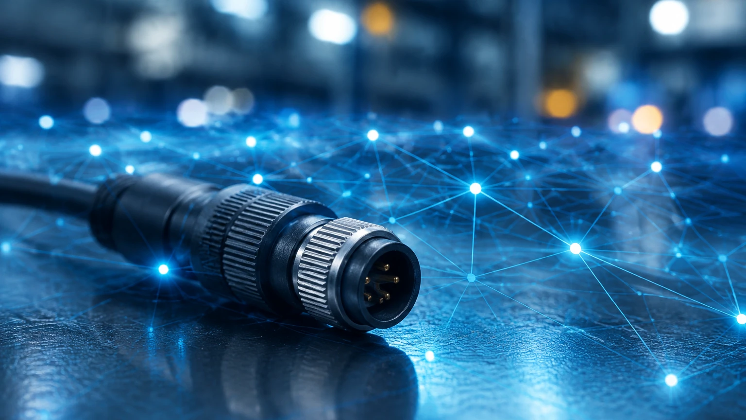
3. Cabling: One of the most significant advantages of the sensor IO-Link standard is the use of standard M12 connectors and unshielded 3-wire cables. This significantly reduces installation costs compared to shielded analog cables.
Comparison: IO-Link vs. Traditional 4-20mA Analog
To evaluate the necessity of IO-Link for a specific application, engineers should compare its capabilities against traditional analog signals.
| Feature | Traditional 4-20mA Analog | Sensor IO-Link |
| :— | :— | :— |
| Signal Type | Analog (Continuous current) | Digital (Bi-directional) |
| Data Transmission | Single value (Level) | Multiple values (Level, Temp, Status) |
| Configuration | Manual (Local display/HART) | Remote (Via PLC or Software) |
| Diagnostics | Limited (Low/High current error) | Detailed (Error codes, Event logs) |
| Cable Requirement | Shielded twisted pair | Unshielded 3-wire |
| Accuracy | Subject to EMI and D/A conversion | High (No conversion loss) |
| Device Replacement | Manual recalibration required | Automatic parameter download |
Practical Selection Criteria for IO-Link Level Sensors
When choosing a sensor for an IO-Link ecosystem, engineers should confirm several technical specifications to ensure compatibility and performance.
* Process Data Length: Check how many bytes of data the sensor transmits. A level sensor might transmit 4 bytes (32 bits) representing the level in millimeters and a status bit.
* Transmission Rate (COM Speed): IO-Link supports three speeds: COM1 (4.8 kbit/s), COM2 (38.4 kbit/s), and COM3 (230.4 kbit/s). Most modern level sensors utilize COM2 or COM3 for faster response times.
* Minimum Cycle Time: This defines how often the master polls the sensor. For fast-changing levels in small tanks, a cycle time of 2.3ms to 5ms is preferable.
* Environment Compatibility: Ensure the sensor’s physical build (IP67/IP68/IP69K) matches the washdown or outdoor requirements of the site. For chemical applications, verify that the wetted parts (e.g., PTFE, 316L Stainless Steel) are resistant to the media.
For a comprehensive range of industrial-grade instruments compatible with modern digital protocols, engineers can Review product options and application support at Welk’s main site.
Installation Considerations and Best Practices
Successful deployment of an IO-Link sensor requires adherence to specific installation guidelines to prevent communication failures.
1. Cable Length Limits: The maximum distance between an IO-Link sensor and the master is 20 meters (approx. 65 feet). If the distance exceeds this, the signal may degrade. For longer distances, a fieldbus-coupled IO-Link master should be placed closer to the process.
2. Port Configuration: IO-Link master ports can often be configured as "Deactivated," "Digital Input (DI)," "Digital Output (DO)," or "IO-Link." Ensure the port is correctly set to IO-Link mode in the PLC configuration tool.
3. Grounding and EMI: While IO-Link is more robust against electromagnetic interference than analog signals, it is still best practice to route communication cables away from high-voltage power lines and variable frequency drives (VFDs).
4. Parameter Storage: Utilize the "Data Storage" feature of the IO-Link master. This allows the master to store the sensor's configuration. If a sensor is damaged and replaced, the master automatically downloads the previous settings to the new device, minimizing downtime.
Limitations and Risks
While IO-Link offers numerous benefits, it is not a universal solution for every scenario. Engineers must be aware of its limitations:
* Bandwidth Constraints: IO-Link is designed for process data and simple diagnostics. It is not suitable for transmitting high-speed waveforms or complex imaging data.
* Distance Restriction: As mentioned, the 20m limit is a hard constraint. For large-scale tank farms where sensors are hundreds of meters from the control room, traditional HART or fieldbus (Foundation Fieldbus/Profibus PA) may be more appropriate.
* Master Dependency: If an IO-Link master fails, all sensors connected to that master lose communication. Redundancy planning at the master level is necessary for critical processes.
* Initial Setup Complexity: For teams accustomed to simple analog wiring, the requirement for IODD files and PLC integration software can present a learning curve.
Frequently Asked Questions (FAQs)
Q: Can I use a standard M12 cable for IO-Link sensors?
Yes, IO-Link is designed to work with standard, unshielded 3-wire or 4-wire M12 cables. This is one of the primary cost-saving benefits of the technology.
Q: Is IO-Link compatible with older PLCs?
IO-Link requires an IO-Link master. If your older PLC supports a fieldbus like PROFINET or Modbus TCP, you can add an IO-Link master as a gateway. If the PLC has no digital communication capabilities, you cannot use IO-Link features.
Q: Can an IO-Link sensor still provide an analog 4-20mA signal?
Many manufacturers offer "hybrid" sensors that feature one IO-Link channel and one traditional analog output or switch output. This is useful for facilities transitioning to digital systems while maintaining local analog displays.
Q: How do I handle IODD files?
IODD files are typically downloaded from the sensor manufacturer's website or an industry-standard IODD finder database. They are then imported into the PLC engineering software (like TIA Portal or Studio 5000) to configure the device.
Conclusion
The transition to sensor IO-Link technology represents a significant step forward in industrial automation. By providing a transparent view into the health and performance of level measurement instruments, IO-Link enables predictive maintenance and reduces the total cost of ownership. Whether deploying radar, ultrasonic, or hydrostatic sensors, the ability to remotely configure and diagnose devices ensures that industrial processes remain efficient, safe, and scalable. For those looking to implement these solutions, selecting high-quality hardware and following rigorous installation standards is the key to long-term success in the digital era.