Plexiglass Dielectric Constant
Plexiglass Dielectric Constant
In the field of industrial level measurement, understanding the electrical properties of materials used in process vessels is critical for instrument accuracy and reliability. One of the most frequently encountered materials in viewports, protective barriers, and specialized tank components is Polymethyl Methacrylate (PMMA), commonly known as plexiglass. For engineers and technicians deploying radar or capacitance-based level sensors, the plexiglass dielectric constant is a fundamental parameter that dictates how electromagnetic waves interact with the material and how the sensor perceives the target medium.
This article provides a comprehensive technical overview of the dielectric properties of plexiglass, its impact on different level measurement technologies, and practical engineering considerations for its use in industrial automation.
The Role of Dielectric Constant in Level Measurement
Before examining plexiglass specifically, it is essential to define the dielectric constant ($ε_r$), also known as relative permittivity. It is a dimensionless ratio that measures a material's ability to store electrical energy in an electric field compared to a vacuum. In the context of level measurement, this property affects two primary technologies: radar (microwave) and capacitance.
Radar Level Measurement Principle
Radar level meters emit high-frequency electromagnetic pulses (typically in the 6 GHz, 26 GHz, or 80 GHz range). These waves travel through the headspace of a tank and reflect off the surface of the stored material. The strength of the reflection is directly proportional to the difference between the dielectric constant of the headspace (usually air or vapor, $ε_r ≈ 1$) and the dielectric constant of the product. If a material has a very low dielectric constant, the radar signal may pass through it rather than reflecting, leading to measurement errors. When a radar signal must pass through a plexiglass window, the plexiglass dielectric constant determines how much of the signal is reflected at the window interface and how much is attenuated as it passes through.
Capacitance Level Measurement Principle
Capacitance sensors treat the probe and the tank wall (or a reference electrode) as two plates of a capacitor. The material between them acts as the dielectric. As the level of the material rises, it displaces the air, changing the total capacitance of the system. If plexiglass is used as an insulating sleeve or a structural component within the sensing field, its dielectric constant must be accounted for in the sensor calibration to ensure accurate level detection.
Technical Specifications: Plexiglass Dielectric Constant Values
Plexiglass is a polar plastic, meaning its dielectric properties are sensitive to frequency and, to a lesser extent, temperature. For engineering calculations, it is important to use the value corresponding to the operating frequency of your instrumentation.
Frequency Dependence
The dielectric constant of PMMA generally decreases as the frequency increases. At low power-line frequencies, the material exhibits higher permittivity due to the ability of the molecular dipoles to align with the slowly oscillating field. At the gigahertz frequencies used by modern radar level meters, the dipoles cannot keep up with the rapid oscillations, resulting in a lower effective dielectric constant.
| Frequency | Typical Dielectric Constant ($ε_r$) | Dissipation Factor (tan δ) |
| :— | :— | :— |
| 50 Hz – 60 Hz | 3.5 – 4.0 | 0.04 – 0.06 |
| 1 MHz | 2.6 – 3.0 | 0.01 – 0.02 |
| 10 GHz – 80 GHz | 2.5 – 2.7 | 0.005 – 0.01 |
For most radar applications, a value of 2.6 is commonly used for plexiglass. This relatively low value makes it a "transparent" material for microwaves, though not as transparent as PTFE (Teflon), which has a dielectric constant of approximately 2.1.
Temperature Effects
Plexiglass maintains a relatively stable dielectric constant within its standard operating temperature range (-40°C to +80°C). However, as the material approaches its glass transition temperature (approximately 105°C), the dielectric constant begins to rise significantly as molecular mobility increases. In industrial level measurement, plexiglass is rarely used in high-temperature applications due to its loss of structural integrity above 85°C.
Radar Level Measurement Through Plexiglass Barriers
In many process environments, it is necessary to isolate the radar antenna from the process media using a "window" or "seal." This is common in highly corrosive environments or when measuring toxic substances where a secondary containment barrier is required.
Signal Attenuation and Refraction
When a radar wave hits a plexiglass barrier, three things happen:
1. Reflection: A portion of the energy reflects off the front and back surfaces of the plexiglass. This can create "ringing" or a "false echo" near the top of the tank.
2. Transmission: The majority of the energy passes through the material.
3. Refraction: The speed of the wave slows down while inside the plexiglass ($v = c / √ε_r$). This causes a slight phase shift and can theoretically affect the calculated distance if the barrier is extremely thick.
The Importance of Thickness
To minimize the reflection from the window itself, engineers often apply the "half-wavelength rule." If the thickness of the plexiglass is an integer multiple of the half-wavelength of the radar signal within the material, the reflections from the front and back surfaces can interfere destructively, effectively canceling each other out and maximizing transmission.
For an 80 GHz radar, the wavelength in air is approximately 3.75 mm. Inside plexiglass ($ε_r = 2.6$), the wavelength is reduced to approximately 2.3 mm. Therefore, a plexiglass window thickness of roughly 1.15 mm (or multiples thereof) would be theoretically optimal, though structural requirements usually dictate thicker dimensions.
Capacitance Level Sensing and Plexiglass Properties
In capacitance level measurement, plexiglass is often used as a mounting flange or a protective shield for the electrode. Because the plexiglass dielectric constant is significantly higher than that of air (1.0) but lower than that of water (80), it acts as a stable insulator.
If a capacitance probe is coated with plexiglass or installed behind a plexiglass plate, the sensor must be calibrated to "zero out" the capacitance contributed by the plexiglass. One risk in these applications is the accumulation of moisture or conductive films on the surface of the plexiglass. Since water has a much higher dielectric constant, even a thin film of condensation can dramatically change the measured capacitance, leading to a false high-level reading. For this reason, plexiglass components in capacitance systems should be designed to shed liquid and avoid "bridging" between the electrode and the tank wall.
Comparative Analysis: Plexiglass vs. Industrial Polymers
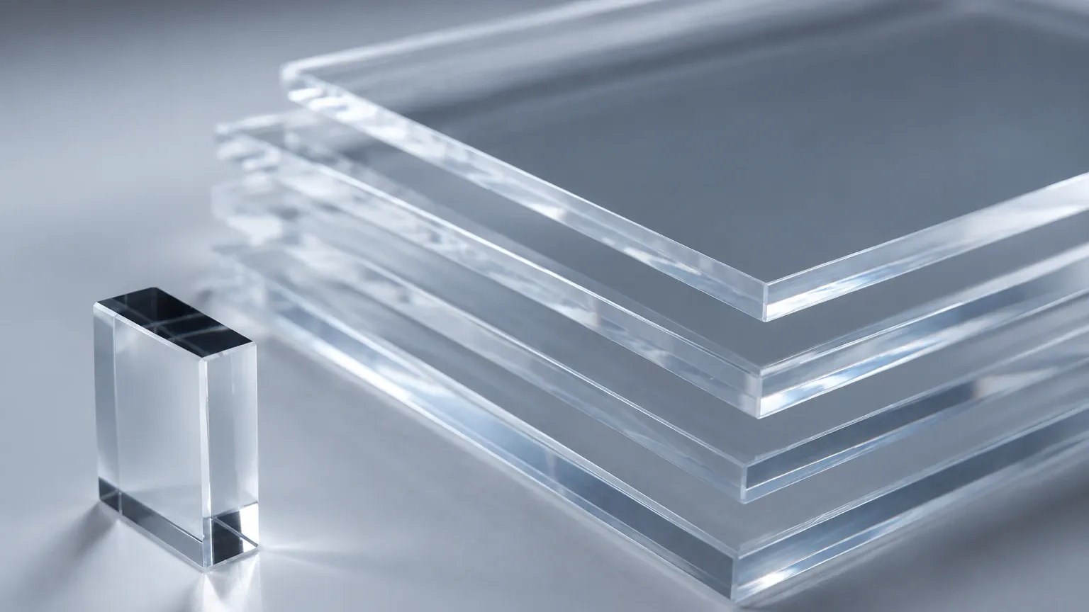
When selecting a material for a viewport or an isolation barrier, engineers must weigh the dielectric constant against chemical resistance and thermal stability. The following table compares plexiglass (PMMA) with other common materials used in level measurement.
| Material | Dielectric Constant ($ε_r$) | Max Operating Temp | Chemical Resistance | Typical Application |
| :— | :— | :— | :— | :— |
| Plexiglass (PMMA) | 2.6 – 3.0 | 80°C | Moderate | Viewports, low-temp radar windows |
| PTFE (Teflon) | 2.1 | 260°C | Excellent | Corrosive chemical radar seals |
| PEEK | 3.2 | 250°C | Excellent | High-pressure/High-temp probes |
| Polypropylene (PP) | 2.3 | 100°C | Good | Water treatment, acid tanks |
| Borosilicate Glass | 4.0 – 4.5 | 450°C | Excellent | High-pressure steam viewports |
While plexiglass offers excellent optical clarity and is cost-effective, its lower thermal ceiling and vulnerability to certain solvents (like acetone or toluene) often limit its use to water-based applications or light industrial processes. For comprehensive technical data on instruments compatible with these materials, engineers can consult the Main Page of professional measurement solution providers.
Engineering Guidelines for Installation and Material Selection
When designing a system that involves level measurement through or near plexiglass, follow these practical engineering guidelines:
1. Angle of Incidence: If using plexiglass as a radar window, avoid mounting the radar antenna perfectly parallel to the window if possible. A slight tilt (typically 2-5 degrees) can help deflect the initial surface reflection away from the antenna's receiver, improving the signal-to-noise ratio for the actual product level.
2. Surface Finish: Ensure the plexiglass surface is smooth. Scratches or pitting can cause scattering of high-frequency radar waves, particularly at 80 GHz, where the wavelength is very short.
3. Condensation Management: In tanks containing warm liquids, condensation will form on the underside of a plexiglass cover. Because water has a high dielectric constant, droplets will reflect radar signals and create "noise." Using a conical or sloped plexiglass design encourages droplets to run off to the sides, clear of the radar beam path.
4. Chemical Compatibility: Before installation, verify that the process vapors will not craze or cloud the plexiglass. A clouded surface might not significantly change the plexiglass dielectric constant, but it often indicates structural degradation that could lead to pressure boundary failure.
5. Thickness and Pressure: Plexiglass is more brittle than polycarbonate. If the plexiglass serves as a pressure-retaining window, ensure the thickness is calculated based on the maximum allowable working pressure (MAWP) and the safety factors required by local codes (e.g., ASME BPVC).
Limitations, Environmental Factors, and Risks
While plexiglass is a versatile material, its use in level measurement has specific limitations:
* UV Degradation: Standard plexiglass can become brittle and yellow when exposed to intense UV radiation over several years. This aging process can slightly alter the dielectric loss factor, though the dielectric constant usually remains stable until physical cracking occurs.
* Static Charge Accumulation: Plexiglass is an excellent insulator and can accumulate significant static charge, especially in dry environments or with flowing non-conductive powders. In explosive atmospheres (ATEX/IECEx zones), this poses a spark risk. Anti-static coatings may be required, but these coatings can have their own dielectric properties that must be accounted for.
* Dielectric Heating: In very high-power microwave applications (rare in standard level measurement), materials with a non-zero dissipation factor like plexiglass can absorb energy and heat up. For low-power industrial radar sensors, this is generally negligible.
Frequently Asked Questions
Q: Does the color of the plexiglass affect its dielectric constant?
A: For most industrial applications, the dyes used in colored or "smoked" plexiglass have a negligible effect on the dielectric constant. However, metallic-flake pigments or carbon-black additives can significantly increase both the dielectric constant and the attenuation (loss), potentially blocking radar signals entirely.
Q: Can a radar level meter see through a 20mm thick plexiglass plate?
A: Yes, but there will be a measurable loss in signal strength. At 20mm, the attenuation is manageable for most high-sensitivity radars, but the internal reflections within the thick plate may create a larger "dead zone" near the sensor. Calibration for "empty tank" mapping is essential in this configuration.
Q: How does moisture absorption affect the plexiglass dielectric constant?
A: PMMA has a water absorption rate of about 0.3% to 2% by weight depending on the grade. While this is low, absorbed moisture will slightly increase the dielectric constant and the dissipation factor. For high-precision laboratory measurements, this must be considered, but for most industrial level applications, the effect is within the sensor's standard margin of error.
Q: Is plexiglass suitable for use with ultrasonic level sensors?
A: No. The plexiglass dielectric constant is irrelevant for ultrasonic sensors, which use sound waves. However, plexiglass is an acoustic barrier. Sound waves will mostly reflect off the surface of the plexiglass rather than passing through it, making it unsuitable as a window for ultrasonic measurement.
Conclusion
The plexiglass dielectric constant is a pivotal factor in the successful integration of radar and capacitance level instruments in industrial environments. By recognizing that the value sits typically between 2.5 and 3.0 at high frequencies, engineers can better predict signal behavior, design effective isolation barriers, and ensure accurate calibration. While plexiglass offers clear advantages in terms of visibility and cost, its thermal and chemical limitations must be balanced against the requirements of the specific process. For those selecting instrumentation for challenging industrial applications, reviewing technical documentation and product options on the Main Page of a specialized manufacturer is the recommended next step to ensure system compatibility and long-term performance.