Hands-on Instrumentation Training
Hands-on Instrumentation Training
In the modern industrial landscape, the accuracy of level measurement is a cornerstone of process safety, inventory management, and operational efficiency. While theoretical knowledge provides the foundation, hands-on instrumentation training is essential for engineers and technicians to master the complexities of field devices. This guide explores the core principles of industrial level measurement, selection criteria for various technologies, and the practical skills required to ensure reliable instrument performance.
Fundamental Principles of Level Measurement
Before engaging in the physical installation or calibration of instruments, it is critical to understand the underlying physical principles of the most common technologies used in industrial automation. Level measurement is generally categorized into continuous measurement and point level detection.
Radar Level Measurement
Radar level meters utilize Time of Flight (ToF) technology. High-frequency electromagnetic waves (typically in the GHz range) are emitted from the antenna, reflected off the surface of the medium, and received back by the sensor. The distance is calculated based on the time taken for the signal to travel.
* Non-contact Radar: Ideal for corrosive or high-temperature media as the sensor does not touch the material.
* Guided Wave Radar (GWR): Uses a probe to guide the signal, making it highly effective for low dielectric constants or turbulent surfaces.
Ultrasonic Level Sensors
Similar to radar, ultrasonic sensors use ToF but rely on mechanical sound waves rather than electromagnetic waves. A transducer emits an ultrasonic pulse that bounces off the product surface. Because sound speed is influenced by air temperature, these sensors usually include integrated temperature compensation.
Hydrostatic Level Transmitters
Hydrostatic measurement is based on the principle that the pressure at the bottom of a liquid column is proportional to the height of that column (P = ρgh). These transmitters measure the head pressure of the liquid and convert it into a level reading. This method is highly reliable for vented tanks and deep wells.
Magnetic Level Gauges
Magnetic gauges are based on the law of communicating vessels and buoyancy. A float containing a permanent magnet moves with the liquid level in a bypass chamber. This magnet flips external flags or interacts with a reed chain to provide a visual or electronic output. This technology is preferred for high-pressure or hazardous applications where direct visual access to the process is required without the risk of glass breakage.
Practical Selection Criteria
Selecting the correct instrument is the first step in successful field implementation. During hands-on instrumentation training, professionals learn that no single technology fits every application. The choice depends on the physical properties of the medium, vessel geometry, and environmental conditions.
| Technology | Suitable Media | Advantages | Limitations |
| :— | :— | :— | :— |
| Radar | Liquids, Solids, Slurries | High accuracy, unaffected by vapor or pressure | Higher initial cost |
| Ultrasonic | Water, Wastewater, Chemicals | Cost-effective, non-contact | Sensitive to foam, heavy dust, and vacuum |
| Hydrostatic | Water, Oils, Chemicals | Simple installation, reliable for deep tanks | Requires constant density for accuracy |
| Magnetic Gauge | Hazardous liquids, Acids | High visibility, no power required for visual | Mechanical moving parts subject to wear |
| Level Switches | Almost all liquids/solids | Reliable point detection (High/Low) | No continuous measurement |
For a comprehensive overview of available technologies and specific model specifications, engineers should refer to the Main Page of professional manufacturers to align application requirements with hardware capabilities.
Hands-on Installation Considerations
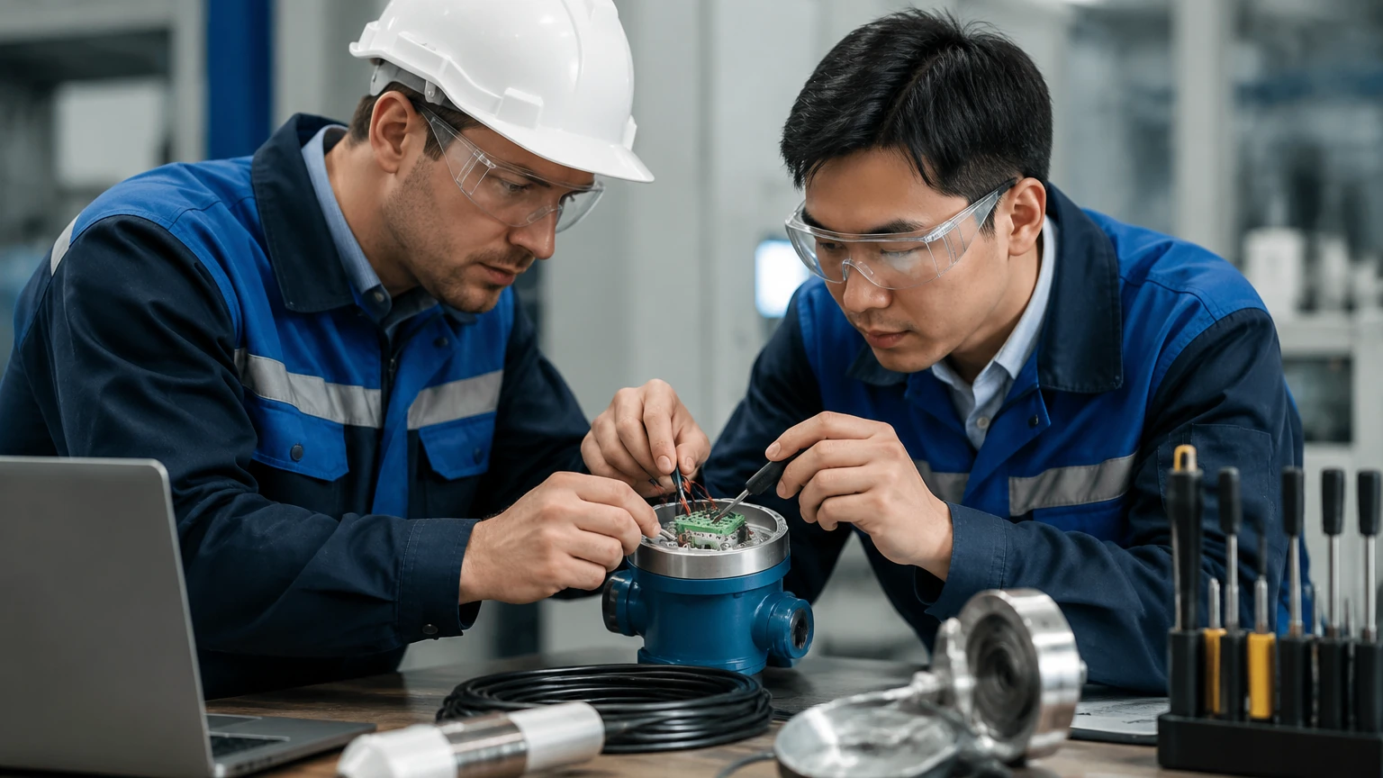
A significant portion of hands-on instrumentation training involves the physical mounting and positioning of sensors. Incorrect installation is the leading cause of signal loss and measurement errors in industrial environments.
Nozzle and Obstruction Management
For radar and ultrasonic sensors, the beam angle is a critical factor. The instrument must be mounted away from the tank wall to prevent false reflections. Furthermore, internal obstructions such as agitators, ladders, or heating coils must be accounted for. If an obstruction is unavoidable, many modern instruments offer "false echo suppression" or "echo mapping" features to ignore these static signals.
Dead Zones (Blocking Distance)
Every ToF sensor has a "dead zone" or blocking distance near the face of the transducer where measurement is impossible. Technicians must ensure the maximum expected level of the medium does not enter this zone. If the tank is frequently filled to the top, a nozzle extension or a different technology may be required.
Pressure and Temperature Limits
Hydrostatic transmitters and magnetic gauges are often used in pressurized vessels. It is vital to verify that the process connections (flanges, threads) and the sensor diaphragms are rated for the maximum operating pressure and temperature. In hydrostatic applications, if the tank is pressurized (not vented to atmosphere), a differential pressure (DP) transmitter must be used to compensate for the top-side pressure.
Calibration and Commissioning Procedures
Once installed, the instrument must be commissioned to translate physical measurements into usable process data (typically a 4-20mA signal or a digital protocol like HART or Modbus).
1. Zero and Span Adjustment: Technicians define the "Zero" point (4mA, usually the bottom of the tank) and the "Span" point (20mA, the maximum fill level).
2. Medium Parameters: For radar, the dielectric constant (Dk) of the material affects signal strength. For hydrostatic sensors, the specific gravity (density) of the liquid must be programmed accurately.
3. Echo Curve Analysis: In advanced hands-on instrumentation training, students use software to view the echo curve of a radar sensor. This allows them to distinguish between the actual level signal and noise caused by turbulence or foam.
4. Loop Testing: Before handing over to operations, a loop test ensures that the signal received at the PLC or DCS matches the local display on the instrument.
Identifying and Mitigating Operational Risks
Field instrumentation is subject to harsh environmental factors that can degrade performance over time. Understanding these risks is a key component of maintenance training.
* Build-up and Coating: In chemical and wastewater applications, material can accumulate on the sensor face or the probe of a GWR. While some radar sensors can penetrate thin layers of build-up, heavy coating will eventually cause signal attenuation.
* Condensation: In humid environments, water droplets can form on ultrasonic transducers, scattering the sound waves. Using sensors with PTFE faces or integrated heaters can mitigate this.
* Turbulence and Foam: Rapid filling or agitation creates surface turbulence. This can scatter radar and ultrasonic signals. In these cases, using a stilling well or a bypass chamber is the standard engineering solution to provide a calm surface for measurement.
Limitations of Level Technologies
No instrument is universal. It is important to recognize the physical boundaries of each technology:
* Ultrasonic sensors cannot function in a vacuum because sound waves require a medium (air/gas) to travel.
* Radar accuracy can be affected by materials with extremely low dielectric constants (e.g., certain liquefied gases) unless a guided wave version is used.
* Hydrostatic sensors will provide incorrect readings if the density of the liquid changes significantly due to temperature fluctuations or mixing of different fluids.
Frequently Asked Questions (FAQ)
Q: How often should level instruments be calibrated?
A: This depends on the criticality of the process and the stability of the environment. Most industrial facilities perform a verification check annually, though high-precision custody transfer applications may require more frequent cycles.
Q: Can I use an ultrasonic sensor for boiling liquids?
A: It is generally not recommended. Boiling creates heavy steam and surface turbulence, both of which interfere with sound wave propagation. Radar is a much more reliable choice for such applications.
Q: What is the benefit of a bypass chamber?
A: A bypass chamber (used with magnetic gauges or GWR) isolates the measurement from the main tank turbulence and allows for maintenance without shutting down the entire process vessel.
Q: Does the color of the liquid affect radar measurement?
A: No. Radar is an electromagnetic measurement and is unaffected by the optical properties (color, transparency) of the medium.
Conclusion
Mastering industrial level measurement requires a balance of theoretical understanding and practical application. Through hands-on instrumentation training, personnel become proficient in selecting the right technology, performing precise installations, and troubleshooting complex signal issues. By adhering to established measurement principles and leveraging advanced diagnostic tools, industrial facilities can ensure long-term reliability and accuracy in their level control loops. For those seeking to explore specific hardware solutions for water treatment, chemical processing, or oil and gas applications, reviewing the latest product options and application support on the Main Page is a recommended next step in the engineering process.