Thermocouple Transmitter
Thermocouple Transmitter
In the landscape of industrial process control, accurate temperature measurement is as critical as pressure or level monitoring. While thermocouples are among the most common sensors used to detect temperature, the raw millivolt signals they produce are inherently fragile and susceptible to electrical noise. A thermocouple transmitter serves as the essential bridge between the primary sensing element and the control system, converting low-level voltage into a robust, standardized signal suitable for long-distance transmission and integration into modern automation architectures.
For engineers managing complex installations—ranging from chemical reactors to water treatment facilities—understanding the nuances of signal conditioning is vital. This guide provides a technical overview of thermocouple transmitter technology, its measurement principles, selection criteria, and its role alongside other process instruments such as radar or ultrasonic level meters.
Measurement Principles and Signal Conditioning
To appreciate the function of a thermocouple transmitter, one must first understand the physics of the thermocouple itself. A thermocouple operates based on the Seebeck effect: when two dissimilar metals are joined at one end (the sensing junction) and exposed to a temperature gradient, a small voltage (electromotive force or EMF) is generated at the open end (the reference junction). This voltage is proportional to the temperature difference between the two junctions.
However, this raw signal presents several challenges for industrial environments:
1. Low Amplitude: The output is typically in the range of microvolts per degree Celsius. Such small signals are easily overwhelmed by electromagnetic interference (EMI) from motors, pumps, and power lines.
2. Non-Linearity: The relationship between temperature and voltage in a thermocouple is not perfectly linear. Each thermocouple type (K, J, T, E, etc.) follows a specific curve defined by international standards (such as IEC 60584).
3. Cold Junction Compensation (CJC): Since the thermocouple measures the difference between the hot junction and the reference junction, the temperature at the point where the thermocouple connects to the measurement instrument must be known and accounted for to determine the absolute temperature of the process.
The Role of the Transmitter
A thermocouple transmitter addresses these issues through four primary functions:
* Amplification: It boosts the millivolt signal to a standard industrial level, most commonly a 4-20 mA current loop. This current signal is far more resistant to line resistance and electrical noise than a voltage signal.
* Linearization: Advanced digital transmitters use internal look-up tables or mathematical algorithms to linearize the non-linear output of the thermocouple, ensuring the output signal (e.g., 4 mA at 0°C and 20 mA at 1000°C) is proportional to the actual temperature.
* Cold Junction Compensation: The transmitter includes an internal temperature sensor (often a thermistor or RTD) at its input terminals to measure the ambient temperature. It then mathematically adds this "cold junction" value to the thermocouple reading to provide an accurate process temperature.
* Galvanic Isolation: High-quality transmitters provide electrical isolation between the input, output, and power supply. This prevents ground loops, which can cause significant measurement errors and protect sensitive control equipment from high-voltage surges.
Types of Thermocouple Transmitters
Transmitters are categorized primarily by their physical form factor and mounting location. The choice depends on the accessibility of the sensor and the environmental conditions of the plant.
Head-Mount Transmitters
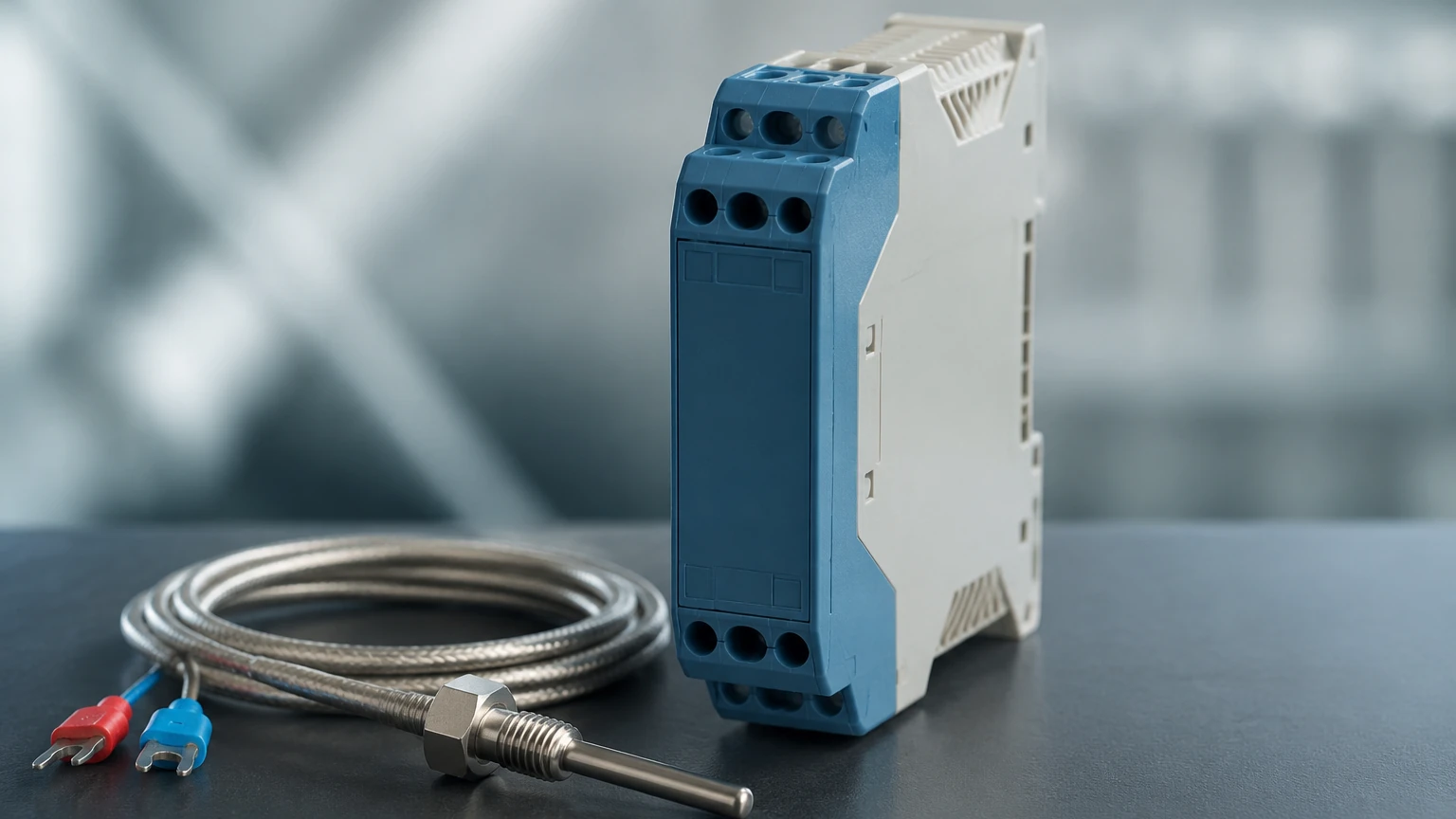
These are small, puck-shaped devices designed to fit directly inside the connection head of a thermocouple probe. By converting the signal at the point of measurement, head-mount transmitters eliminate the need for expensive thermocouple extension wires over long distances, replacing them with standard twisted-pair copper wire.
DIN Rail Mount Transmitters
Installed within a control cabinet or junction box, these modules are mounted on standard 35mm DIN rails. They are preferred when multiple sensors are concentrated in one area or when the environment at the process point is too harsh (extreme heat or vibration) for electronics. They often offer easier access for maintenance and calibration.
Field-Mount Transmitters
These are housed in rugged, often explosion-proof or weather-proof enclosures (IP66/67). They are designed for the most demanding environments, such as oil and gas refineries or offshore platforms, where the transmitter must be located near the process but exposed to the elements.
Technical Selection Criteria
Selecting the correct thermocouple transmitter requires an evaluation of both the process requirements and the existing control infrastructure. Use the following table as a baseline for comparing common configurations.
Selection Table: Transmitter Comparison
| Feature | Head-Mount | DIN Rail Mount | Field-Mount |
| :— | :— | :— | :— |
| Typical Location | Inside sensor terminal head | Control room or local cabinet | Mounted on pipe or wall near process |
| Wiring Requirement | Copper wire to controller | Extension wire to cabinet | Copper wire to controller |
| Environmental Protection | Dependent on sensor head | Usually IP20 (requires cabinet) | IP66/67, NEMA 4X, Explosion-proof |
| Ease of Maintenance | Moderate (requires opening head) | High (centralized location) | Moderate (rugged housing) |
| Best For | Reducing wiring costs | High-density installations | Hazardous or outdoor areas |
Key Specifications to Confirm
1. Input Versatility: Does the transmitter support multiple thermocouple types (K, J, R, S, B, N, T, E)? Universal transmitters allow for easier inventory management.
2. Output Signal: While 4-20 mA is the standard, some applications may require 0-10V or digital protocols like HART (Highway Addressable Remote Transducer), Foundation Fieldbus, or PROFIBUS. HART-enabled transmitters are particularly useful for remote diagnostics and configuration.
3. Accuracy and Stability: Look for the "Total Probable Error," which includes the effects of linearization, CJC accuracy, and ambient temperature drift. High-precision applications may require a drift specification of less than 0.01% of span per degree Celsius.
4. Response Time: In fast-moving thermal processes, the damping or update rate of the transmitter can impact the control loop's stability.
Installation Considerations and Best Practices
Proper installation is as important as the hardware itself. Even the most accurate thermocouple transmitter can produce erroneous data if the installation environment is not managed correctly.
Wiring and Grounding
* Extension Wires: If the transmitter is not head-mounted, you must use the correct thermocouple extension wire between the sensor and the transmitter. Using standard copper wire here will create new, unintended junctions, leading to massive errors.
* Shielding: Use shielded cables for the 4-20 mA loop to protect against EMI. The shield should generally be grounded at only one end (usually the control system end) to avoid ground loops.
* Separation: Keep signal wires away from high-voltage power cables. If they must cross, do so at a 90-degree angle.
Environmental Protection
Transmitters are electronic devices. While field-mount versions are rugged, head-mount and DIN rail versions must be protected from moisture and corrosive gases. In chemical processing plants, ensure the housing materials are compatible with the local atmosphere.
Integration with Level Measurement
In many industrial tanks, temperature and level measurement go hand-in-hand. For example, when using hydrostatic level transmitters, the density of the liquid changes with temperature. A thermocouple transmitter provides the real-time temperature data needed for the control system to calculate a density-corrected level. Similarly, in gas-filled spaces where ultrasonic level sensors operate, temperature fluctuations change the speed of sound, making accurate temperature compensation essential for precise distance measurement. For a comprehensive range of instruments that work in tandem with temperature systems, engineers can Review product options and application support to ensure full system compatibility.
Limitations and Common Risks
While highly reliable, thermocouple transmitters have limitations that engineers must account for during the design phase:
* Sensor Degradation: Thermocouples drift over time due to oxidation or contamination of the metal junctions (especially at high temperatures). The transmitter cannot "fix" a failing sensor; it can only report the signal it receives. Regular calibration of the sensor-transmitter pair is required.
* Burnout Detection: If a thermocouple wire breaks, the transmitter should have a configurable "burnout" setting—either driving the signal high (e.g., 21.5 mA) or low (e.g., 3.8 mA)—to alert the control system of the failure. Failure to configure this can lead to dangerous "stuck" readings.
* Ambient Temperature Limits: Most transmitters have an operating range (typically -40°C to +85°C). If a head-mount transmitter is used on a high-temperature furnace without sufficient thermal lagging or a long enough sensor nipple, the electronics may overheat and fail.
Frequently Asked Questions (FAQs)
Q: Can I use a thermocouple transmitter with an RTD sensor?
A: Many modern transmitters are "universal" and can be configured for either thermocouples or RTDs (Resistance Temperature Detectors). However, you must check the specific model’s datasheet, as the wiring and measurement principles differ significantly.
Q: Why use a 4-20 mA transmitter instead of connecting the thermocouple directly to a PLC?
A: While some PLCs have thermocouple input cards, using a transmitter is often superior because it converts the signal to 4-20 mA early. This reduces the cost of expensive extension wire, improves noise immunity, and allows the signal to travel hundreds of meters without degradation.
Q: How often should a thermocouple transmitter be calibrated?
A: In most industrial applications, an annual calibration check is standard. However, in critical safety applications or high-accuracy processes, semi-annual checks may be necessary. Digital transmitters often require less frequent calibration than older analog models.
Q: What is the difference between isolated and non-isolated transmitters?
A: Isolated transmitters have an internal barrier that prevents electrical current from flowing between the input and output circuits. This is crucial if the thermocouple is "grounded" (physically touching the metal sheath), as it prevents ground loop currents from distorting the signal.
Conclusion
The thermocouple transmitter is a fundamental component in modern process automation, ensuring that critical temperature data remains accurate and reliable as it moves from the harsh conditions of the process floor to the control room. By selecting the appropriate mounting style, ensuring robust galvanic isolation, and following strict installation guidelines, facilities can minimize downtime and improve process efficiency. Whether used as a standalone monitor or as part of a complex system involving level, pressure, and flow measurement, the transmitter remains the primary line of defense against signal interference and measurement error.