Thermal Mass Flow Controller
Thermal Mass Flow Controller
In the landscape of industrial process automation, the ability to precisely measure and control the movement of gases is fundamental to product quality, safety, and operational efficiency. A thermal mass flow controller (MFC) is a sophisticated instrument designed to not only measure the mass flow rate of a gas but also to automatically control that flow to a specific setpoint. Unlike volumetric flow meters, which are influenced by changes in temperature and pressure, the thermal mass flow controller provides a direct measurement of mass, making it an essential tool in applications ranging from semiconductor manufacturing to chemical vapor deposition and pharmaceutical bioreactors.
As a professional manufacturer of industrial level measurement instruments, Welk recognizes that flow and level control often operate in tandem within complex automated systems. Whether managing the headspace gas in a storage tank or ensuring the precise delivery of reagents in a water treatment facility, understanding the underlying principles of thermal mass flow technology is critical for engineering success.
Measurement Principles of Thermal Mass Flow
Thermal mass flow controllers operate based on the thermal properties of the gas being measured—specifically, its heat capacity. There are two primary methods used in industrial thermal mass flow measurement: the capillary tube (bypass) method and the immersion (industrial) method. Most high-precision MFCs used in laboratory and light industrial settings employ the capillary tube principle.
The Capillary Tube Principle
In this design, a small portion of the total gas flow is diverted through a narrow capillary tube (the sensor tube). The main flow passes through a laminar flow element (bypass) that ensures the ratio between the sensor flow and the bypass flow remains constant across the instrument's operating range.
Two resistance temperature detectors (RTDs) are wound around the exterior of the capillary tube, with a heating element positioned between them. When there is no flow, the heat from the central element radiates equally to both RTDs, resulting in a zero temperature difference. As gas begins to flow through the tube, it carries heat away from the upstream sensor and toward the downstream sensor. This creates a temperature differential ($ΔT$) that is directly proportional to the mass flow rate of the gas. The electronic circuitry converts this $ΔT$ into a linear electrical signal.
The Thermal Dispersion Principle
Used more frequently in heavy industrial applications and large-diameter pipes, this method involves two probes immersed directly into the flow stream. One probe is heated, while the other serves as a reference sensor for the process temperature. The cooling effect of the gas as it passes over the heated probe is measured. To maintain a constant temperature difference between the two probes, the instrument must increase the power to the heater. This electrical power consumption is directly proportional to the mass flow rate.
Components and Control Logic
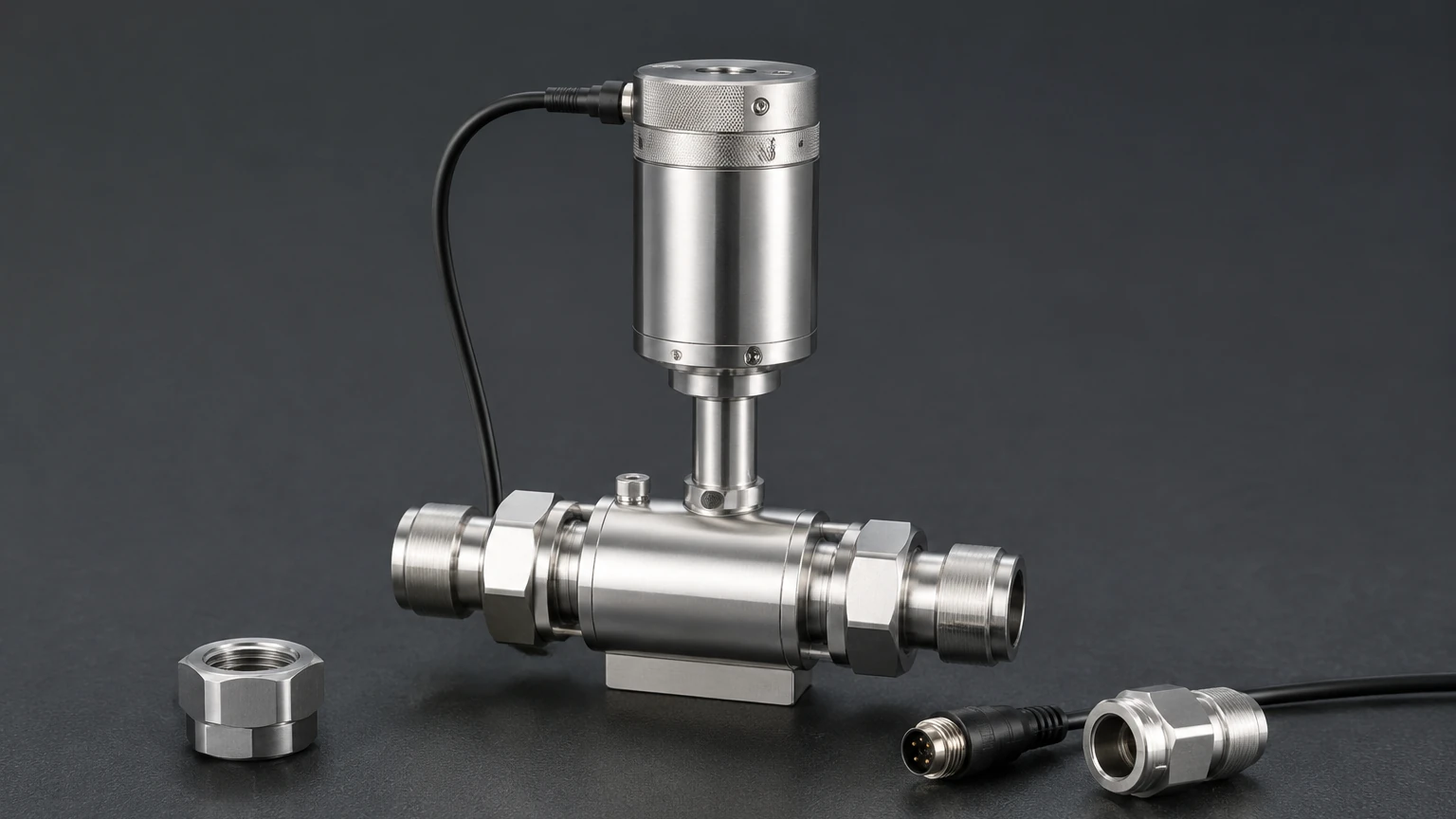
A thermal mass flow controller is an integrated system consisting of three main components: the flow sensor, the control valve, and the electronic control circuitry.
1. The Sensor: As described above, it provides the mass flow measurement signal.
2. The Control Valve: Usually a proportional solenoid valve or a piezo-actuated valve. Unlike a standard on/off valve, the MFC valve can be held at any position between fully open and fully closed to modulate the flow.
3. The Electronics (PID Control): The heart of the MFC is the Proportional-Integral-Derivative (PID) controller. It compares the "setpoint" (the desired flow rate provided by the user) with the "process variable" (the actual flow measured by the sensor). If a discrepancy exists, the PID loop adjusts the current to the control valve to bring the actual flow into alignment with the setpoint, typically within milliseconds.
For engineers looking to integrate these devices into broader process architectures, including those requiring advanced level monitoring, reviewing comprehensive Main Page resources can provide insights into how flow and level data are aggregated in modern control systems.
Technical Selection Criteria
Selecting the correct thermal mass flow controller requires a detailed understanding of the process environment. Because thermal sensors are gas-dependent, a controller calibrated for Nitrogen will not provide accurate readings for Argon without applying a conversion factor or recalibration.
Key Evaluation Factors
* Gas Compatibility: Specify the exact gas or gas mixture. Corrosive gases like Chlorine require specialized sensor materials (e.g., Hastelloy or 316L Stainless Steel) and specialized elastomers (e.g., Kalrez).
* Flow Range: MFCs are characterized by their Full Scale (FS) range. It is standard practice to select a unit where the normal operating flow is between 30% and 70% of the FS range to maintain optimal accuracy.
* Accuracy and Repeatability: High-end MFCs typically offer accuracy of ±0.5% to ±1% of the setpoint. Repeatability is equally important for batch-to-batch consistency.
* Pressure Drop: The instrument itself causes a drop in pressure. Ensure the supply pressure is high enough to overcome the pressure drop of the MFC at maximum flow while still meeting the downstream process requirements.
* Communication Protocols: Modern industrial environments utilize digital interfaces such as EtherCAT, Profibus, Modbus TCP/IP, or DeviceNet, alongside traditional 4-20mA or 0-5V analog signals.
Selection Table: MFC vs. Alternative Technologies
| Feature | Thermal MFC | Rotameter (Variable Area) | Differential Pressure (DP) |
| :— | :— | :— | :— |
| Measurement Type | Direct Mass Flow | Volumetric | Volumetric (Inferred) |
| Control Capability | Integrated Automatic Control | Manual Only | Requires External Valve/PLC |
| Accuracy | High (±1% Setpoint) | Moderate (±2-5% FS) | Moderate (±1-3% FS) |
| Pressure Sensitivity | Low | High | High |
| Moving Parts | One (Valve Plunger) | One (Float) | None |
| Cost | Higher | Low | Moderate |
Installation Considerations
To ensure the longevity and accuracy of a thermal mass flow controller, specific installation protocols must be followed. Failure to adhere to these guidelines often results in "drift" or premature valve failure.
Gas Cleanliness and Filtration
Thermal MFCs, particularly those using capillary sensors, are highly sensitive to particulates and moisture. A 20-micron filter (or finer) should be installed upstream of the MFC. If the gas contains condensable vapors, the gas lines and the MFC itself may need to be heat-traced to prevent liquid from entering the sensor or the valve seat.
Mounting Orientation
While many modern digital MFCs can be mounted in any orientation, they are typically calibrated in a horizontal position. Mounting a high-flow MFC vertically can introduce a small "chimney effect" where heat rises, potentially affecting the zero-point stability. Always consult the manufacturer's data sheet if vertical mounting is required.
Straight Pipe Runs
For immersion-style thermal meters, straight pipe runs of 10 to 20 diameters upstream and 5 diameters downstream are usually required to ensure a fully developed laminar flow profile. For capillary-style MFCs, this is less critical due to the internal bypass design, but avoiding elbows immediately before the inlet is still a best practice.
Leak Integrity
In applications involving toxic or flammable gases, leak integrity is paramount. MFCs are usually helium leak-tested to rates of $1 × 10^{-9}$ atm-cc/sec. Ensure that the fittings (typically VCR, VCO, or compression fittings like Swagelok) are installed to the correct torque specifications.
Limitations and Common Risks
Despite their versatility, thermal mass flow controllers are not suitable for every application. Engineers should be aware of the following limitations:
* Gas Composition Shifts: If the gas mixture changes unexpectedly, the thermal conductivity and heat capacity of the medium change. This renders the factory calibration invalid. Digital MFCs with multi-gas functionality can mitigate this by allowing the user to select different gas profiles from a pre-loaded library.
* Zero Drift: Over time, the zero-point of the sensor may shift due to temperature cycles or electronic aging. Regular "zeroing" of the instrument under no-flow conditions is required for maintained precision.
* Valve Stiction: If the gas is not perfectly clean, residues can build up on the valve seat, causing the valve to stick or respond sluggishly. This is a common issue in chemical deposition processes.
* Response Time vs. Stability: There is often a trade-off between how fast an MFC reaches its setpoint and the stability of the flow. A PID loop tuned for ultra-fast response may cause the flow to overshoot or oscillate.
Frequently Asked Questions (FAQ)
Q: Can a thermal mass flow controller be used for liquids?
A: Generally, no. Thermal mass flow *controllers* are designed specifically for gases. While thermal mass *meters* exist for liquids, the control valve dynamics and the heat transfer coefficients are significantly different, requiring specialized equipment.
Q: What is the difference between SLM and LPM?
A: LPM (Liters per Minute) is a volumetric measurement that changes with pressure and temperature. SLM (Standard Liters per Minute) refers to the mass of gas that would occupy one liter at a standard temperature and pressure (typically 0°C and 101.325 kPa, though definitions of "standard" can vary by industry).
Q: How often should an MFC be recalibrated?
A: For most industrial applications, an annual calibration is recommended. However, in critical semiconductor or pharmaceutical processes, semi-annual or even quarterly verification may be required to meet regulatory standards.
Q: Does the supply pressure affect the flow rate?
A: A thermal mass flow controller is designed to maintain a constant mass flow regardless of moderate fluctuations in upstream pressure, provided that the pressure remains within the valve's operating differential. If the pressure drops too low, the valve will open fully (100%), but the device will be unable to reach the setpoint.
Conclusion
The thermal mass flow controller is a cornerstone of modern gas process control, providing the precision and automation necessary for high-stakes industrial applications. By understanding the thermal dispersion principles and carefully evaluating gas-specific requirements, engineers can select a device that ensures long-term stability and accuracy. For those managing broader industrial systems, integrating reliable flow control with advanced level measurement solutions is the key to achieving total process transparency. For further technical specifications and product options across the measurement spectrum, engineers are encouraged to consult the Main Page for detailed application support and instrument selection guides.