Level Switch High High
Level Switch High High
In industrial process control and safety engineering, the level switch high high (LSHH) represents a critical layer of protection. While a standard high-level alarm (LSH) typically alerts operators to a deviation from normal operating parameters, the LSHH is designed as a safety-critical secondary or tertiary defense mechanism. Its primary function is to trigger an emergency shutdown (ESD) or provide overfill protection to prevent environmental contamination, equipment damage, or hazardous material release.
Selecting and implementing an effective LSHH system requires a deep understanding of measurement principles, media characteristics, and the regulatory requirements governing Safety Instrumented Systems (SIS). This guide provides an engineering perspective on the technologies, selection criteria, and installation practices for high-high level detection.
Measurement Principles for High-High Detection
Before selecting a specific instrument for an LSHH application, it is essential to understand the underlying physical principles. Since LSHH switches often remain dormant for long periods—only acting during an emergency—they must be inherently reliable and capable of self-diagnosis.
Vibrating Fork (Tuning Fork) Principles
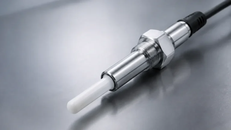
Vibrating fork level switches utilize a piezoelectric crystal to energize a fork-shaped sensor at its natural resonant frequency. When the fork is immersed in a liquid, the frequency shifts significantly. This shift is detected by the internal electronics and converted into a switching signal. Because they have no moving parts and are largely unaffected by flow, turbulence, or bubbles, they are a preferred choice for LSHH applications.
Float and Magnetic Principles
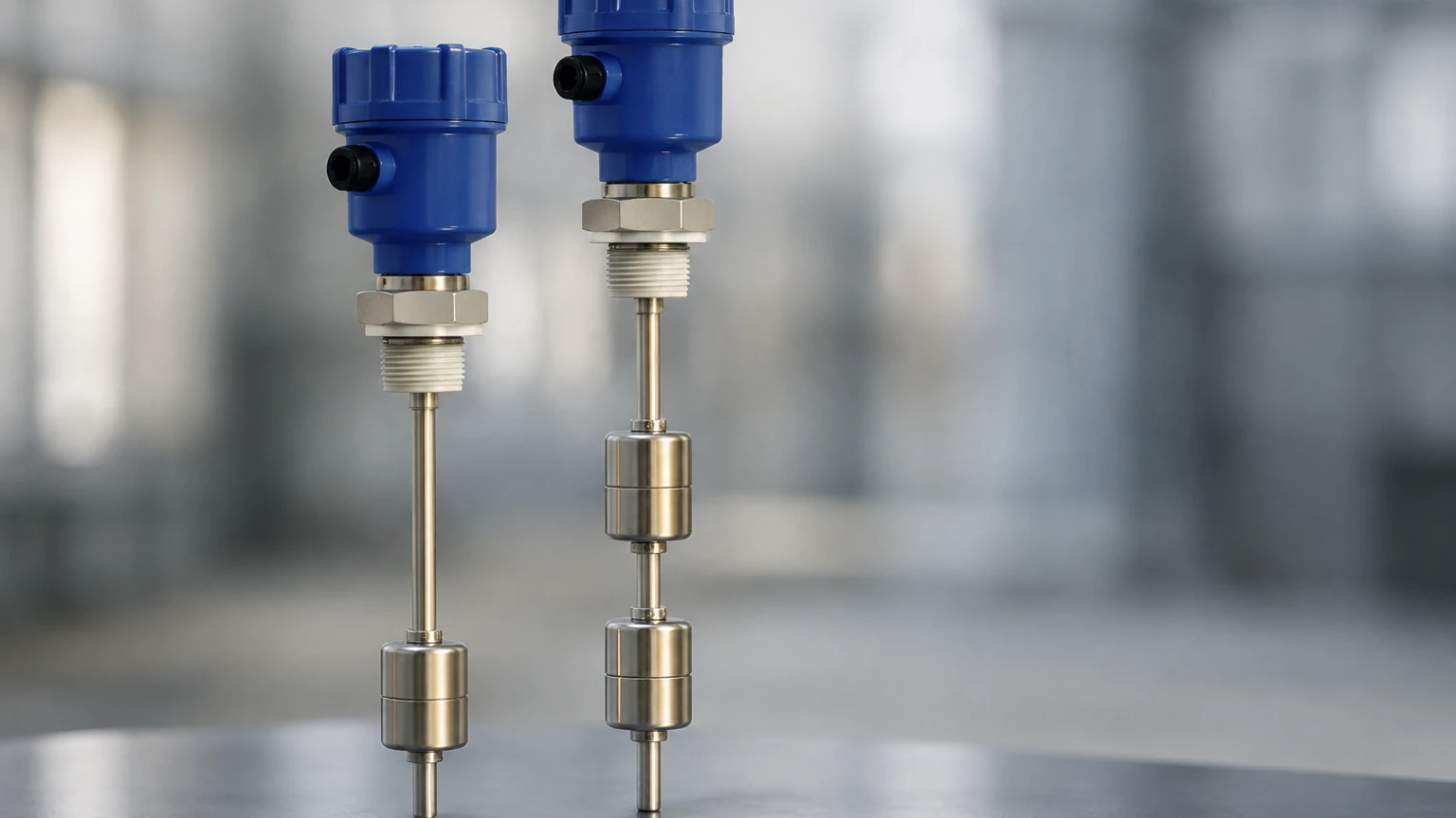
Float switches rely on buoyancy. A float containing a magnet moves along a stem as the liquid level rises. When the float reaches a predetermined point, the magnetic field actuates a reed switch or a microswitch. While mechanically simple, these are generally reserved for clean, non-coating liquids in LSHH roles due to the risk of mechanical sticking in viscous or dirty media.
Capacitance Principles
Capacitive level switches measure the change in electrical capacitance between an electrode and the tank wall (or a reference probe). As the liquid displaces air, the dielectric constant changes, altering the capacitance. These are robust and can handle high temperatures and pressures, though they often require calibration specific to the media.
Ultrasonic and Optical Principles
Ultrasonic switches use high-frequency sound waves to detect the presence of liquid at a specific gap in the sensor head. Optical switches use the refraction of infrared light. Both are non-mechanical and offer fast response times, though they can be sensitive to foam or heavy coating on the sensor face.
Distinguishing LSH from LSHH
In most process designs, level management is categorized into three or four distinct zones. Understanding the hierarchy is vital for proper system configuration.
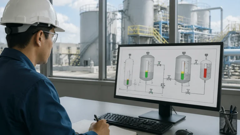
1. Normal Operating Level: The range where the process is controlled by a continuous level transmitter (e.g., radar or hydrostatic).
2. Level Switch High (LSH): The first alarm point. It notifies the operator that the level is higher than desired, allowing for manual or automated control adjustments (e.g., opening a discharge valve).
3. Level Switch High High (LSHH): The safety threshold. If the level reaches this point, it implies the control system and the LSH have failed. The LSHH typically bypasses the standard control logic to initiate a hard-wired shutdown of inlet pumps or the closure of isolation valves.
For engineers seeking specific hardware for these safety layers, the Main Page offers a technical breakdown of instruments rated for various safety integrity levels.
Technology Selection Criteria
Choosing the right level switch high high depends on the physical and chemical properties of the process medium. The following table summarizes common technologies and their suitability for LSHH applications.
| Technology | Media Suitability | Advantages | Limitations |
| :— | :— | :— | :— |
| Vibrating Fork | Liquids, light slurries | Self-monitoring, no moving parts, high reliability. | Not suitable for extremely high-viscosity media that bridges the forks. |
| Displacer/Float | Clean, non-scaling liquids | Low cost, simple operation, no power required (passive). | Susceptible to mechanical failure/jamming; requires regular movement checks. |
| Capacitance | Acids, alkalis, high-pressure steam | Robust construction, handles extreme temperatures (up to 400°C+). | Requires media with a stable dielectric constant; sensitive to buildup. |
| Ultrasonic Gap | Clean liquids, oils | No moving parts, very fast response. | Can be affected by aeration or dense foam. |
| Conductivity | Conductive liquids (water-based) | Very inexpensive, simple. | Only works with conductive media; probes can corrode or foul. |
Installation and Engineering Considerations
An LSHH switch is only as reliable as its installation. To ensure the safety loop performs as intended, several engineering guidelines should be followed:
Independence and Redundancy
For high-risk applications, the LSHH switch should be physically independent of the primary level transmitter. It should ideally use a separate process connection (nozzle) to prevent a single point of failure—such as a clogged tap—from disabling both the control and safety systems.
Orientation and Mounting
* Side Mounting: Common for vibrating forks. Ensure the forks are oriented correctly (usually vertically) so that liquid can drain freely and not collect between the tines.
* Top Mounting: Preferred for float or ultrasonic probes. Ensure the probe length is precisely calculated to trigger at the exact LSHH setpoint, accounting for the height of the mounting nozzle.
Stilling Wells
In tanks with heavy agitation or turbulence, a stilling well (a vertical pipe) should be used to protect the switch. This prevents "chatter"—rapid toggling of the switch—which can cause unnecessary wear on pumps and contactors.
Fail-Safe Configuration
LSHH switches should always be configured in a "fail-safe" mode. This means the circuit should be closed (energized) when the level is safe and open (de-energized) when the high-high level is reached or if power is lost. This ensures that a broken wire or power failure triggers a safety response rather than leaving the system unprotected.
Limitations and Common Risks
Despite their importance, LSHH systems are subject to specific risks that must be managed through maintenance and design.
* Media Buildup: In sticky or crystallizing fluids, material can accumulate on the sensor. Vibrating forks are generally resistant to this, but heavy "bridging" can cause a false positive or prevent the sensor from detecting the liquid.
* Testing Gaps: Since LSHH switches rarely activate, they can fail "silently." Without regular proof testing, the operator may not know the switch is dead until an actual overfill occurs.
* Chemical Compatibility: The wetted parts (316L stainless steel, Hastelloy, PTFE, etc.) must be compatible with the process fluid to prevent corrosion-induced failure.
Frequently Asked Questions (FAQ)
Q: What is the difference between an LSHH and an Overfill Prevention System (OPS)?
A: An LSHH is a specific switch or setpoint within a system. An Overfill Prevention System is the entire functional loop, including the sensor (LSHH), the logic solver, and the final control element (e.g., an automated valve).
Q: How often should an LSHH switch be tested?
A: This is determined by the Safety Integrity Level (SIL) calculation for the plant. Typically, proof testing occurs every 6 to 24 months. Some modern vibrating forks include "partial stroke testing" or self-diagnostic features that reduce the manual testing interval.
Q: Can a continuous radar transmitter be used for LSHH?
A: Yes, a radar transmitter can provide an LSHH output. However, for high-SIL applications, it is often required to have a diverse technology (e.g., a radar for control and a vibrating fork for LSHH) to avoid common-cause failures.
Q: What is a "Dry Run" in the context of LSHH?
A: A dry run refers to testing the switch's functionality without actually filling the tank. This is often done using a test magnet (for float switches) or an internal electronic test button (for vibrating forks) to simulate a high-high condition.
Final Considerations for Project Specification
When specifying a level switch high high, engineers must confirm the following data points before procurement:
1. Process Conditions: Maximum pressure (bar) and temperature (°C).
2. Media Properties: Density, viscosity, and chemical composition.
3. Tank Geometry: Nozzle size, height, and internal obstructions (e.g., agitators).
4. Electrical Requirements: Output type (Relay, PNP/NPN, or 8/16mA loop) and hazardous area certifications (ATEX, IECEx).
By adhering to these factual boundaries and selection criteria, industrial facilities can ensure that their LSHH systems provide the necessary protection for personnel and assets. For further technical specifications and product comparisons, reviewing the options on the Main Page is a recommended step in the engineering design process.