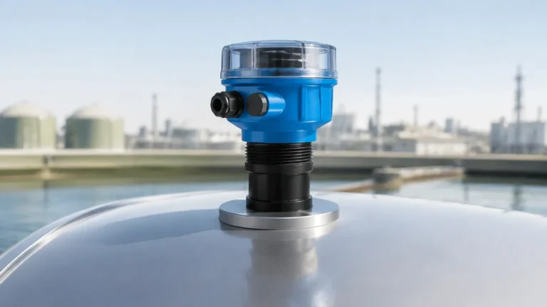
Ultrasonic Water Level Sensor Circuit Diagram
Ultrasonic Water Level Sensor Circuit Diagram: A Technical Guide to Industrial Implementation
In industrial automation and water management, the ability to monitor liquid levels without physical contact is a significant advantage. Ultrasonic technology has emerged as a primary solution for this requirement, offering a balance of accuracy, reliability, and cost-effectiveness. Whether an engineer is designing a custom monitoring system or integrating a pre-built instrument, understanding the ultrasonic water level sensor circuit diagram and the underlying physics is essential for successful deployment.
This guide explores the measurement principles, the functional architecture of the internal circuitry, and the practical considerations for selecting and installing Ultrasonic Level Meters in professional environments.
Understanding Ultrasonic Level Measurement Principles
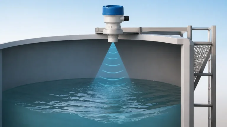
Before examining the circuit architecture, it is necessary to understand the physics of the measurement. Ultrasonic sensors operate on the principle of "Time of Flight" (ToF).
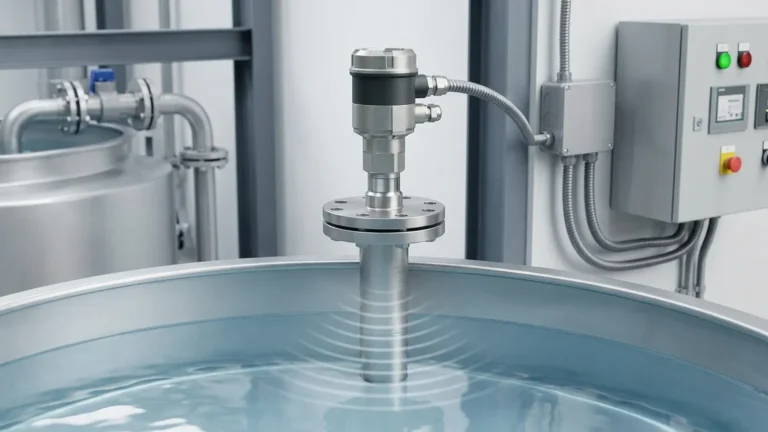
The device emits a high-frequency sound pulse—typically between 40 kHz and 200 kHz—from a piezoelectric transducer. This sound wave travels through the air, reflects off the surface of the water, and returns to the transducer, which now acts as a receiver.
The distance ($D$) between the sensor and the water surface is calculated using the formula:
$$D = \frac{v \times t}{2}$$
Where:
* $v$ is the speed of sound in the medium (approximately 343 m/s in air at 20°C).
* $t$ is the total time elapsed from emission to reception.
The division by two accounts for the round-trip travel of the pulse. In industrial applications, the circuit must translate this distance into a standard signal, such as a 4-20mA current loop, to indicate the actual level of the tank or reservoir.
Functional Components of an Ultrasonic Water Level Sensor Circuit
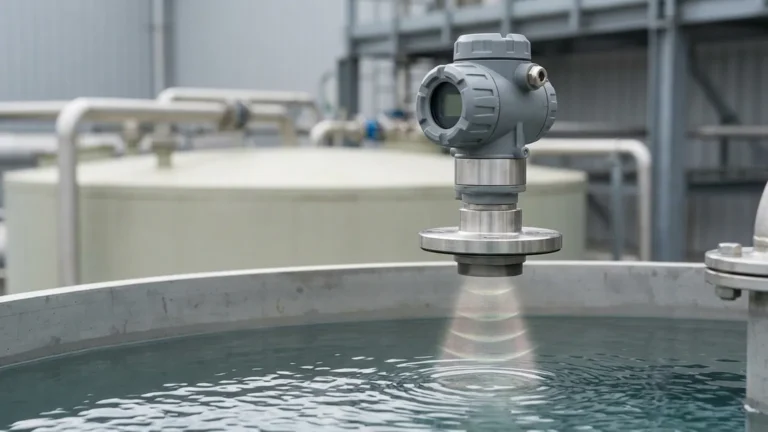
An industrial-grade ultrasonic level meter is more than just a transducer; it is a complex electronic system designed to operate in harsh environments. The ultrasonic water level sensor circuit diagram can be broken down into four primary functional blocks:
1. The Transducer and Driver Stage
The heart of the circuit is the piezoelectric transducer. The driver stage must generate a high-voltage pulse (often 100V to 400V peak-to-peak) for a few microseconds to excite the crystal. This requires a specialized transformer or a high-speed switching circuit to convert the low-voltage DC supply into the necessary excitation energy.
2. Signal Processing and Filtering
The returning echo is extremely weak and often buried in noise. The receiver circuit includes a high-gain pre-amplifier, followed by band-pass filters tuned to the transducer's resonant frequency. Modern circuits utilize Digital Signal Processing (DSP) to distinguish the true surface echo from false reflections caused by tank walls, ladders, or agitators.
3. Microcontroller (MCU) Logic
The MCU manages the timing of the pulses, performs the distance calculation, and applies temperature compensation. Since the speed of sound varies with air temperature (changing by approximately 0.6 m/s per degree Celsius), an integrated thermistor provides real-time temperature data to the MCU to maintain accuracy.
4. Output Interface
For industrial integration, the MCU controls an output stage. This is usually a Digital-to-Analog Converter (DAC) that drives a 4-20mA current loop or a communication chip for RS485 (Modbus RTU) or HART protocols.
Analyzing the Ultrasonic Water Level Sensor Circuit Diagram
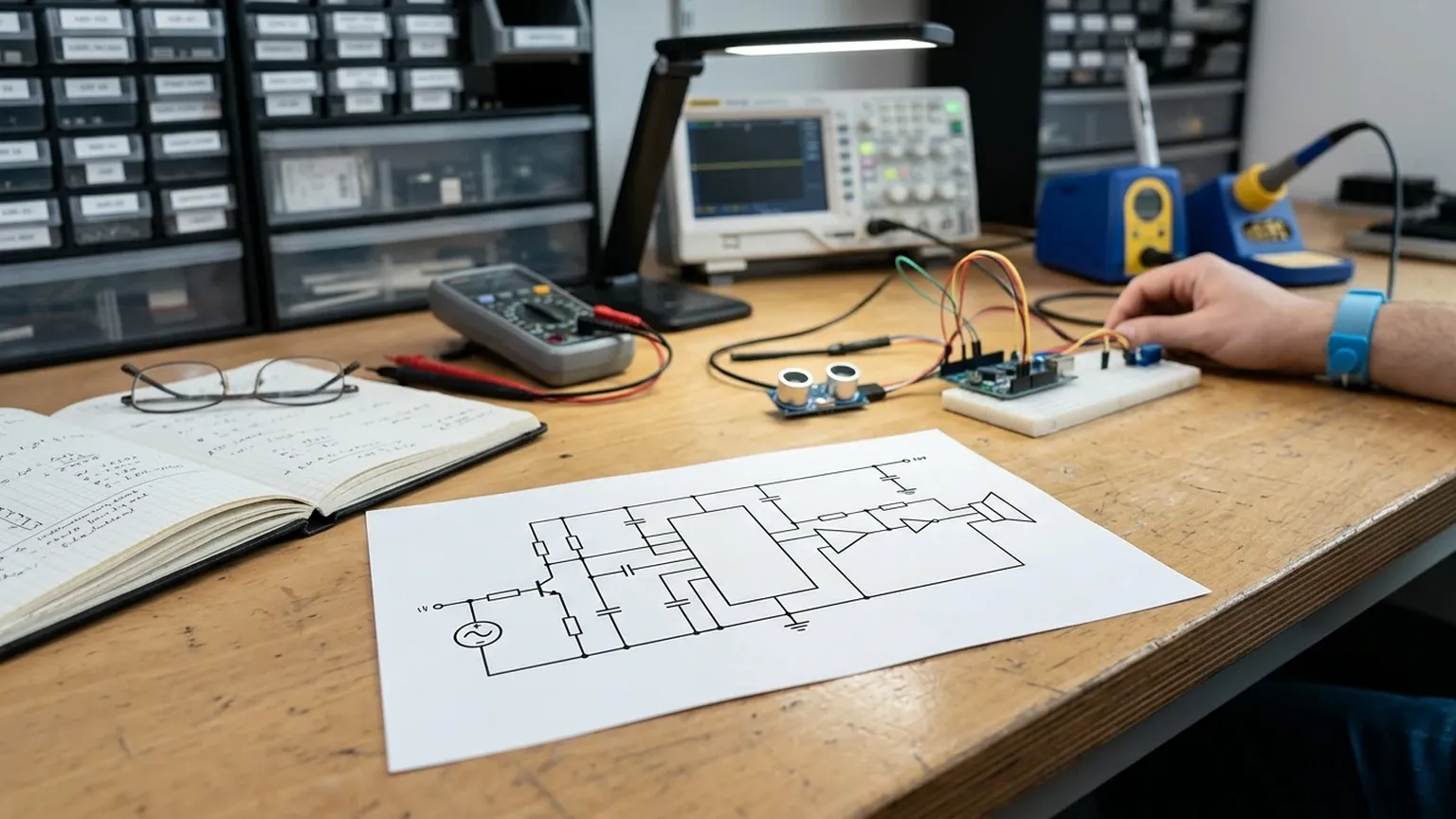
When reviewing a professional ultrasonic water level sensor circuit diagram, several critical design choices become apparent. Unlike hobbyist modules (like the HC-SR04), industrial circuits prioritize power stability and signal integrity.
Power Supply Architecture
Industrial units typically operate on a 24V DC supply. The internal circuit includes a DC-DC converter to step this down to 5V or 3.3V for the MCU, while simultaneously boosting it for the transducer driver. Robust electromagnetic interference (EMI) filtering is included at the power input to prevent industrial noise from affecting the measurement.
Protection Circuitry
In a B2B context, reliability is paramount. The circuit diagram will include:
* Reverse Polarity Protection: Prevents damage if the power leads are swapped.
* Surge Protection: TVS diodes to protect against voltage spikes from nearby heavy machinery.
* Isolation: Galvanic isolation between the sensor electronics and the output loop to prevent ground loops.
Output Loop (4-20mA)
The 4-20mA output is the industry standard because it is resistant to electrical noise over long distances. The circuit must be calibrated so that 4mA represents an empty tank (maximum distance) and 20mA represents a full tank (minimum distance).
Industrial Selection Criteria for Ultrasonic Systems
When choosing between different Ultrasonic Level Meters, engineers must evaluate the hardware based on the specific requirements of the application. The following table summarizes key evaluation criteria:
| Feature | Specification Range | Application Context |
| :— | :— | :— |
| Measurement Range | 0.3m to 30m | Depends on tank height or well depth. |
| Beam Angle | 5° to 12° | Narrower beams are better for confined spaces. |
| Accuracy | ±0.2% to ±0.5% | Critical for inventory management and billing. |
| Operating Temperature | -40°C to +70°C | Essential for outdoor or process-heavy environments. |
| Output Options | 4-20mA, RS485, Relays | Determines compatibility with PLC/SCADA systems. |
| Enclosure Rating | IP65 to IP68 | Determines resistance to dust and water immersion. |
Installation Guidelines for Reliable Measurements
Even a perfectly designed ultrasonic water level sensor circuit diagram will fail if the physical installation is incorrect. Proper mounting is the most critical factor in achieving stable readings.
1. The Dead Zone (Blocking Distance)
Every ultrasonic sensor has a "dead zone" immediately in front of the transducer face where it cannot measure. This is the time required for the transducer to stop vibrating after the pulse is emitted. For example, if a sensor has a 0.25m dead zone, the water surface must never come closer than 0.25m to the sensor face.
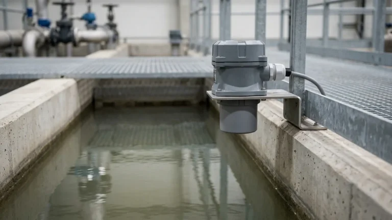
2. Mounting Position and Orientation
* Perpendicularity: The sensor must be mounted perfectly perpendicular to the water surface. A tilt of even a few degrees can cause the echo to bounce away from the receiver.
* Wall Interference: The sensor should not be mounted too close to the tank wall. The ultrasonic beam spreads as it travels; if it hits the wall, it creates false echoes.
* Obstructions: Ensure the path is clear of pipes, ladders, or brackets.
3. Stilling Wells
In applications with surface turbulence or foam, a stilling well (a vertical pipe) can be used. The pipe acts as a guide for the sound wave and provides a calm surface for measurement, though the circuit must be calibrated to account for the pipe's internal reflections.
Limitations and Environmental Factors
While ultrasonic sensors are versatile, they are not universal. Engineers must be aware of the following limitations:
* Foam: Heavy surface foam absorbs ultrasonic pulses rather than reflecting them, leading to signal loss.
* Vacuum: Sound waves require a medium (air/gas) to travel. Ultrasonic sensors cannot function in a vacuum.
* Vapor and Dust: High concentrations of heavy vapors or dense dust can attenuate the signal and change the speed of sound, leading to inaccuracies.
* High Pressure: Changes in pressure affect the density of the air, which in turn affects the speed of sound. Most standard ultrasonic meters are rated for atmospheric pressure.
Comparison: Prototyping Modules vs. Industrial Integrated Meters
For B2B applications, it is important to distinguish between the basic ultrasonic water level sensor circuit diagram used for education and the integrated instruments provided by manufacturers like Welk.
| Feature | Prototyping Module (e.g., HC-SR04) | Industrial Meter (Welk) |
| :— | :— | :— |
| Housing | Exposed PCB | IP67/IP68 Sealed Enclosure |
| Signal Processing | Basic Threshold | Advanced DSP / False Echo Suppression |
| Temp. Compensation | Rarely Included | Integrated Thermistor + Algorithm |
| Calibration | Manual Coding | Push-button or Software Interface |
| Longevity | Low (Months) | High (Years) |
| Connectivity | TTL Logic (5V) | 4-20mA, Modbus, HART |
Frequently Asked Questions (FAQs)
Q: Can I use an ultrasonic sensor to measure solids?
A: Yes, but with caution. Solids like grain or sand often form a conical shape, which can scatter the ultrasonic beam. Sensors for solids usually require higher power and specific signal processing algorithms.
Q: How do I handle a tank with an agitator?
A: Most industrial ultrasonic circuits allow you to program "masking" zones. This tells the MCU to ignore echoes returning from a specific distance (where the agitator blades are located).
Q: Is the 4-20mA output loop-powered?
A: Many modern ultrasonic level meters are 2-wire loop-powered, meaning they draw their operating power directly from the 4-20mA signal line. Others are 3-wire or 4-wire, requiring a separate power supply.
Q: What is the maximum distance an ultrasonic sensor can measure?
A: For water, industrial sensors can typically reach up to 30 meters. Beyond that, the signal attenuation in the air becomes too great, and radar technology is usually preferred.
Conclusion
Designing or implementing an ultrasonic water level sensor circuit diagram requires a deep understanding of both electronics and acoustics. While the basic principle of Time of Flight is simple, the transition to a reliable industrial tool involves sophisticated signal processing, temperature compensation, and robust physical housing. By selecting high-quality Ultrasonic Level Meters and following rigorous installation standards, organizations can ensure accurate and maintenance-free level monitoring for their water treatment, chemical, and automation processes.
Download Ultrasonic Water Level Sensor Circuit Diagram as a PDF