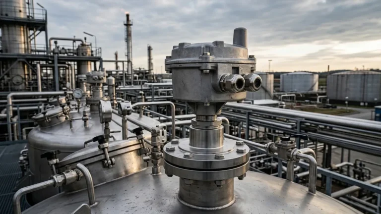
Ultrasonic Level Element
Understanding the Ultrasonic Level Element in Industrial Process Control
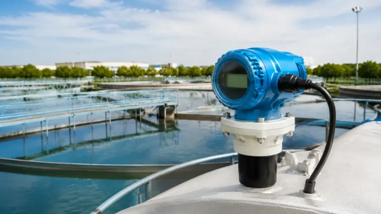
In the field of industrial automation, precise inventory management and process safety rely heavily on accurate level measurement. Among the various technologies available, the ultrasonic level element has emerged as a cornerstone for non-contact liquid and solid level monitoring. As a core component of modern Ultrasonic Level Meters, the element—often referred to as the transducer—is responsible for both the emission of acoustic energy and the detection of reflected signals.
For engineers and procurement professionals, understanding the nuances of the ultrasonic level element is essential for ensuring long-term reliability in applications ranging from municipal water treatment to complex chemical processing. This guide examines the fundamental physics, selection criteria, and practical installation requirements for these critical instruments.
Measurement Principles of the Ultrasonic Level Element
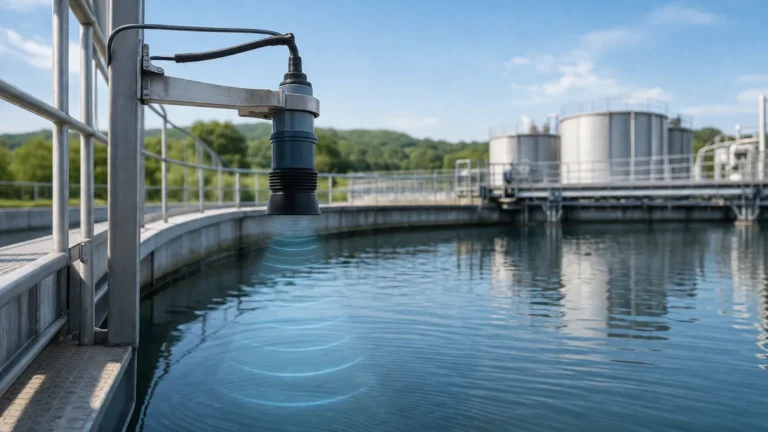
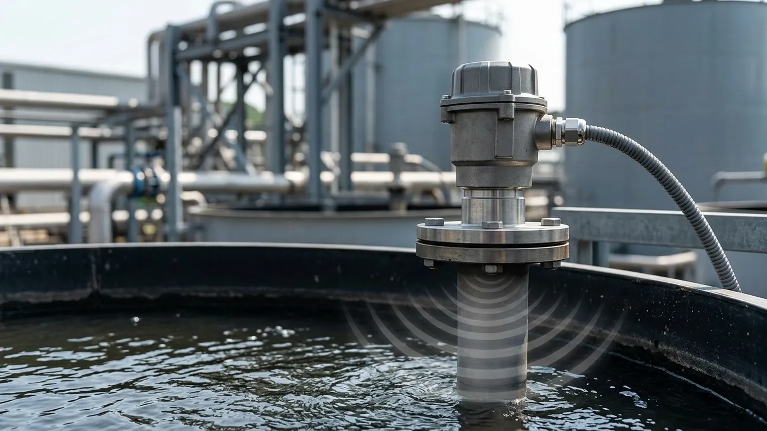
The operation of an ultrasonic level element is based on the "Time-of-Flight" (ToF) principle. This method measures the time it takes for an ultrasonic pulse to travel from the sensor to the surface of the medium and back again.
1. Signal Generation and Reception
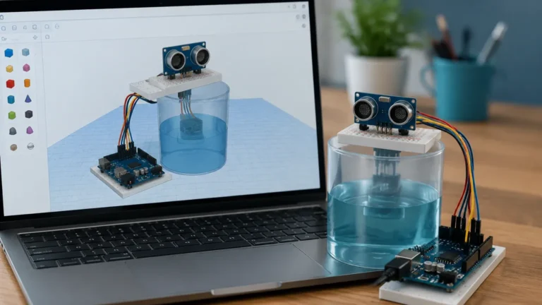
The ultrasonic level element contains a piezoelectric crystal. When an electrical pulse is applied to this crystal, it vibrates at a specific frequency (typically between 20 kHz and 80 kHz), creating a mechanical sound wave. This wave travels through the air or gas space in the tank. When the wave reaches the surface of the material being measured—whether a liquid, slurry, or solid—a portion of the energy is reflected back toward the element.
Upon returning, the reflected echo causes the piezoelectric crystal to vibrate again, converting the mechanical energy back into an electrical signal. The integrated electronics then process this signal to determine the distance.
2. The Distance Calculation
The distance between the ultrasonic level element and the material surface is calculated using the following formula:
D = (v × t) / 2
Where:
* D is the distance to the surface.
* v is the velocity of sound in the medium (usually air).
* t is the total time elapsed between the pulse emission and echo reception.
Since the pulse travels to the surface and back, the total distance is divided by two to find the distance from the sensor face to the product level. The meter then subtracts this distance from the total tank height (the calibration point) to provide the actual level or volume.
3. Temperature Compensation
The speed of sound in air is approximately 331.5 m/s at 0°C, but it increases by about 0.6 m/s for every degree Celsius increase in temperature. Because industrial environments are subject to temperature fluctuations, a high-quality ultrasonic level element must include an integrated temperature sensor. This allows the device to automatically compensate for changes in sound velocity, ensuring measurement accuracy remains within specified tolerances (typically ±0.25% of the range).
Key Evaluation Criteria for Selection
Selecting the correct ultrasonic level element requires a balance between the physical properties of the application and the technical specifications of the sensor. The following factors are critical during the specification phase:
Frequency and Measuring Range
There is an inverse relationship between the frequency of the ultrasonic pulse and the maximum measuring range.
* High-frequency elements (60–80 kHz): These have shorter wavelengths, allowing for higher resolution and smaller "dead zones" (blocking distances). However, high-frequency waves attenuate more quickly in the air, limiting their range to typically 3 to 6 meters.
* Low-frequency elements (20–40 kHz): These pulses carry more energy and can penetrate dust or steam more effectively, reaching distances of up to 30 or 40 meters. The trade-off is a larger sensor size and a longer dead zone.
Beam Angle
The beam angle defines the conical area covered by the ultrasonic pulse. A narrower beam angle (e.g., 5° to 10°) is preferable because it minimizes the risk of the signal hitting internal tank obstructions like ladders, agitators, or weld seams. Elements with wider beam angles are generally easier to align but require a clear path to the surface.
Material Compatibility
The housing and face of the ultrasonic level element must be compatible with the process environment. Common materials include:
* Polypropylene (PP): Suitable for general water and wastewater applications.
* PVDF (Polyvinylidene Fluoride): Highly resistant to corrosive chemicals and acids.
* PTFE (Teflon): Used for extreme chemical resistance and to prevent material buildup on the sensor face.
Practical Selection Table
| Application Type | Recommended Range | Frequency | Housing Material | Key Consideration |
| :— | :— | :— | :— | :— |
| Small Chemical Dosing Tank | 0.25m – 4m | 60-80 kHz | PVDF | Chemical vapor resistance |
| Open Channel Flow (Flumes) | 0.3m – 5m | 50-60 kHz | PP / UV Stable | Accuracy and sun shielding |
| Large Water Reservoir | 1m – 15m | 30-40 kHz | PP / Stainless | Signal strength over distance |
| Grain or Solid Silo | 2m – 20m | 20-30 kHz | Aluminum / Poly | Dust penetration and beam angle |
| Sumps and Wet Wells | 0.5m – 8m | 40-50 kHz | PP / IP68 | Submergence protection |
Installation Considerations and Best Practices
The performance of an ultrasonic level element is often determined more by its installation than by its internal electronics. To ensure reliable data, engineers should follow these guidelines:
1. Respect the Blocking Distance (Dead Zone)
Every ultrasonic level element has a "dead zone" directly in front of the transducer face where it cannot accurately measure. This occurs because the crystal needs time to stop vibrating after the pulse is emitted before it can listen for the return echo. If the liquid level enters this zone, the meter may provide erratic readings or lock onto a high-level error. Always mount the sensor high enough so that the maximum liquid level never enters the dead zone.
2. Positioning and Orientation
* Perpendicularity: The sensor face must be installed perfectly parallel to the liquid surface. A tilt of even a few degrees can cause the reflected echo to bounce away from the transducer, resulting in signal loss.
* Wall Proximity: Do not mount the element too close to the tank wall. The ultrasonic beam expands as it travels; if it hits the wall, it may create "ghost echoes" that confuse the processing electronics.
* Inflow Avoidance: Never install the sensor directly above the tank's filling inlet. The turbulence and air entrainment from the incoming liquid will scatter the signal.
3. Use of Standpipes
In tanks with heavy foam or extreme turbulence, installing the ultrasonic level element inside a standpipe (stilling well) can provide a calm surface for measurement. The pipe acts as a waveguide, focusing the signal and eliminating surface ripples. However, the pipe must be smooth and free of burrs to prevent false reflections.
Limitations and Environmental Constraints
While highly versatile, the ultrasonic level element is not a universal solution. Certain physical conditions can impede its performance:
* Vacuum Conditions: Sound waves require a medium (gas) to travel. In a vacuum, ultrasonic pulses cannot propagate, making these sensors unusable.
* Heavy Foam: Dense foam acts as an acoustic absorber. Instead of reflecting the signal, the foam absorbs it, leading to a "Loss of Echo" (LOE) error. In such cases, radar or hydrostatic transmitters may be more appropriate.
* High Pressure and Temperature: High pressure increases the density of the gas, changing the speed of sound. While some compensation is possible, extreme pressures can damage the transducer seal. Similarly, temperatures exceeding 80°C to 100°C can degrade the piezoelectric elements over time.
* Dust and Vapor: While low-frequency sensors can handle some dust, extremely thick dust or heavy steam can attenuate the signal. Welk provides specialized high-power transducers for these environments, but site-specific testing is often recommended.
Frequently Asked Questions (FAQs)
Q: Can an ultrasonic level element measure solids?
A: Yes, but with limitations. Solids like grain or plastic pellets have an angle of repose, which can reflect the signal away from the sensor. Additionally, solids absorb more sound than liquids. A lower frequency element and a swivel mounting bracket are usually required to aim the sensor at the optimal reflection point.
Q: How do I handle internal obstructions like agitators?
A: Modern Ultrasonic Level Meters feature "False Echo Suppression" or "Echo Mapping." During commissioning, the user can instruct the meter to record all static reflections (from pipes or agitator blades) while the tank is empty. The software then ignores these specific distances during operation.
Q: Does the color of the liquid affect the measurement?
A: No. Unlike optical sensors, ultrasonic technology is completely unaffected by the color, transparency, or dielectric constant of the liquid. It only requires a surface that can reflect a sound wave.
Q: What maintenance is required for these sensors?
A: Because they are non-contact, maintenance is minimal. However, in applications with heavy condensation or splashing, the sensor face should be periodically wiped clean to prevent buildup that could dampen the vibrations of the piezoelectric crystal.
Conclusion
The ultrasonic level element remains one of the most cost-effective and reliable tools for industrial level monitoring. By understanding the relationship between frequency, environment, and installation geometry, process engineers can implement solutions that provide years of maintenance-free service. When selecting an instrument, always verify the chemical compatibility of the wetted materials and ensure the chosen range accounts for the necessary blocking distance at the top of the vessel. For complex applications involving vapor or turbulence, consulting with a specialized manufacturer like Welk ensures that the selected ultrasonic level element is optimized for the specific challenges of the site.