Ultrasonic V
Ultrasonic V
In the field of industrial automation, precision is governed by the laws of physics. For engineers and plant managers, understanding the variables that influence sensor performance is critical to maintaining process integrity. One of the most significant variables in non-contact level measurement is the speed of sound, often represented in physics as ultrasonic v (velocity).
Ultrasonic Level Meters have become a staple in water treatment, chemical processing, and oil and gas industries because they offer a non-contact solution that reduces maintenance and prevents contamination. However, the accuracy of these devices is entirely dependent on how the system manages the velocity of the acoustic pulse as it travels through the vapor space of a tank or vessel.
The Fundamental Measurement Principle
Before selecting or installing a device, it is essential to understand the underlying mechanics of ultrasonic technology. Ultrasonic level measurement is based on the "Time-of-Flight" (ToF) principle.
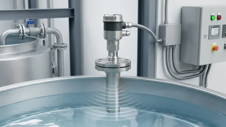
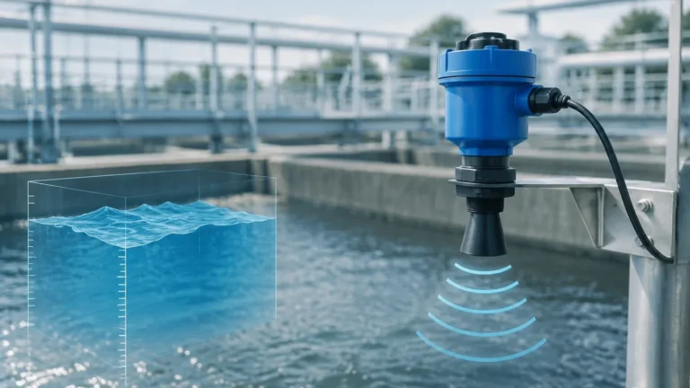
The sensor, or transducer, contains a piezoelectric crystal that converts electrical energy into mechanical vibrations, emitting a high-frequency sound pulse. This pulse travels through the air (or gas) until it hits the surface of the material being measured. It then reflects back to the transducer, which now acts as a receiver.
The distance ($D$) between the sensor and the material surface is calculated using the following formula:
$$D = \frac{v \cdot t}{2}$$
Where:
- $D$ is the distance to the surface.
- $v$ is the velocity of sound in the medium (the ultrasonic v factor).
- $t$ is the total time elapsed from emission to reception.
Because the pulse must travel to the surface and back, the product of velocity and time is divided by two. The level of the material is then determined by subtracting this distance from the total height of the tank (the calibration point).
Understanding the Ultrasonic V Factor: Velocity Influences
The velocity of sound is not a constant; it fluctuates based on the environment through which it travels. If the velocity is assumed to be a fixed value (such as 344 m/s at 20°C in air) while the actual conditions change, the resulting level reading will be inaccurate.
1. Temperature Variations
Temperature is the most significant factor affecting sound velocity in air. As temperature increases, air molecules move faster, allowing the sound wave to propagate more quickly. The relationship is approximately:
$$v \approx 331.5 + 0.6 \cdot T$$
(Where $T$ is the temperature in degrees Celsius).
A change of just 1°C can result in a 0.17% error in distance measurement. In a 10-meter (approx. 32.8 ft) silo, an uncompensated temperature shift of 10°C could lead to an error of 17 cm (6.7 inches). To mitigate this, high-quality Ultrasonic Level Meters include integrated temperature sensors within the transducer to provide real-time compensation.
2. Gas Composition
The speed of sound varies drastically depending on the gas medium. While most industrial applications involve air, tanks containing heavy vapors (like Carbon Dioxide) or light gases (like Hydrogen) will change the ultrasonic v significantly. For example, sound travels at approximately 259 m/s in $CO_2$, compared to 344 m/s in air. If a meter calibrated for air is used in a $CO_2$ environment without adjustment, the error will exceed 20%.
3. Atmospheric Pressure and Humidity
Under normal industrial conditions, changes in atmospheric pressure have a negligible effect on the speed of sound. However, humidity does play a minor role. High humidity increases the density of the air slightly, which can increase the velocity. In most standard applications, temperature compensation is sufficient to maintain an accuracy of ±0.25% of the range.
Practical Selection Criteria
Choosing the right instrument requires matching the sensor's frequency and build material to the specific application environment. Lower frequency sensors (e.g., 20 kHz) have longer ranges and better penetration through dust or steam, while higher frequency sensors (e.g., 60 kHz) offer higher resolution for short-range, precision tasks.
Selection Table: Ultrasonic Meter Specifications
| Application Type | Recommended Frequency | Measuring Range | Housing Material | Key Feature |
| :— | :— | :— | :— | :— |
| Water/Wastewater | 40 – 50 kHz | 0.4m – 15m | ABS / PVC | IP68 Waterproof |
| Corrosive Chemicals | 40 kHz | 0.3m – 10m | PVDF / PTFE | Acid/Alkali Resistance |
| Large Silos/Solids | 20 kHz | 2.0m – 40m | Cast Aluminum | High Power Pulse |
| Small Process Tanks | 60 – 80 kHz | 0.2m – 5m | Stainless Steel | Narrow Beam Angle |
Installation Considerations for Optimal Performance
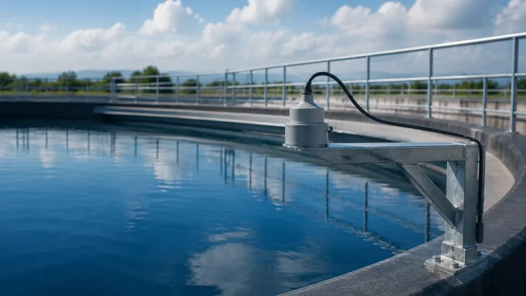
Even the most advanced Ultrasonic Level Meters will fail if installed incorrectly. To ensure the ultrasonic v path is clear and reflections are accurate, follow these engineering guidelines:
1. Avoid the "Dead Zone": Every ultrasonic sensor has a blocking distance (dead zone) near the transducer face where it cannot receive signals. Ensure the maximum material level never enters this zone, typically 0.2m to 0.5m (8 to 20 inches) depending on the model.
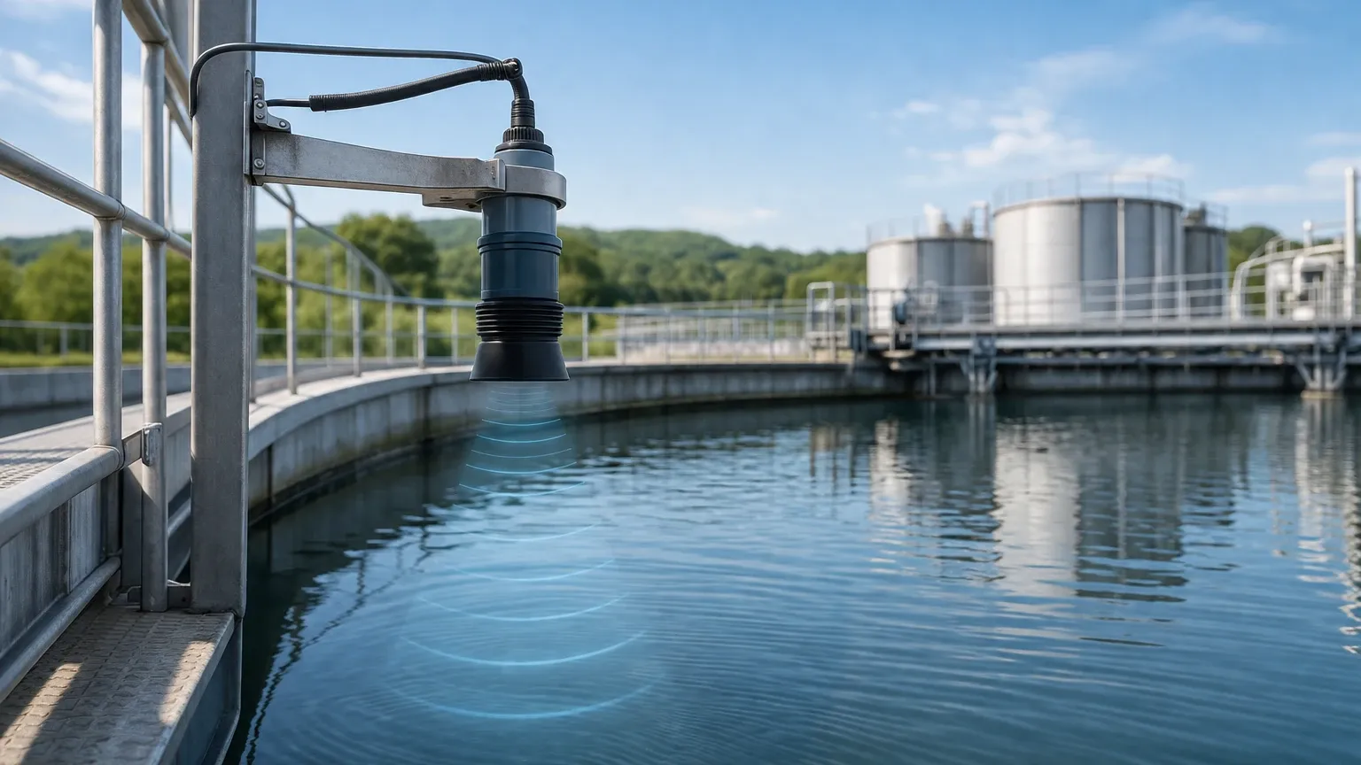
2. Beam Path Clearance: The ultrasonic pulse spreads out in a cone shape (usually 5° to 12°). Ensure there are no obstructions like ladders, pipes, or agitators within this cone. If obstructions are unavoidable, many modern meters offer "False Echo Suppression" software to ignore these static reflections.
3. Perpendicular Alignment: The transducer face must be mounted perfectly parallel to the liquid surface. If the sensor is tilted, the sound energy will reflect away from the receiver, resulting in a "Loss of Echo" error.
4. Nozzle Height: If mounting on a standpipe or nozzle, ensure the pipe is wide enough and short enough that the beam does not hit the pipe walls before exiting into the tank.
Limitations and Prohibitions
While ultrasonic technology is versatile, it is not a universal solution. Engineers should be aware of the following limitations:
* Vacuum Environments: Sound requires a medium to travel. In a vacuum, the ultrasonic v is zero, making these meters non-functional.
* High Foam: Heavy, dense foam absorbs the acoustic signal rather than reflecting it. For applications with thick foam blankets, radar or hydrostatic transmitters are preferred.
* Extreme Temperatures: Most ultrasonic transducers are limited to environments below 80°C (176°F). High temperatures can damage the piezoelectric element and create significant air turbulence that scatters the sound wave.
* High Pressure: In high-pressure gas environments, the increased density can attenuate the signal, though some specialized high-pressure models exist.
Frequently Asked Questions (FAQ)
Q: How does wind or air turbulence affect the reading?
A: Strong air currents can "blow" the sound wave away or cause fluctuations in the temperature gradient, leading to unstable readings. In outdoor tanks, a stilling well or a protective sunshade is recommended to stabilize the environment around the sensor.
Q: Can ultrasonic meters measure solids?
A: Yes, but with caveats. Solids like grain, coal, or plastic pellets do not reflect sound as efficiently as liquids. They often have an "angle of repose," which can deflect the signal. For solids, it is best to use a high-power, low-frequency sensor and aim it toward the middle of the slope.
Q: What is the difference between a 2-wire and 4-wire ultrasonic meter?
A: A 2-wire meter is loop-powered (the same two wires provide power and the 4-20mA signal), making it easier to install but offering less processing power. A 4-wire meter has separate power and signal lines, allowing for higher-intensity pulses and more complex signal processing, which is ideal for difficult applications.
Q: Does the color or transparency of the liquid matter?
A: No. Unlike optical or laser sensors, ultrasonic waves rely on mechanical reflection. The color, transparency, or dielectric constant of the liquid does not affect the measurement, provided the surface is reflective.
Conclusion
Achieving reliable level measurement requires more than just installing a sensor; it requires an understanding of the physical environment and the factors affecting ultrasonic v. By accounting for temperature, gas composition, and proper physical installation, Welk’s Ultrasonic Level Meters provide a robust, cost-effective solution for modern industrial needs.
When selecting a meter, always verify the chemical compatibility of the transducer face and ensure the chosen frequency matches the required range and environmental conditions. With proper engineering oversight, ultrasonic technology remains one of the most reliable methods for non-contact process control.