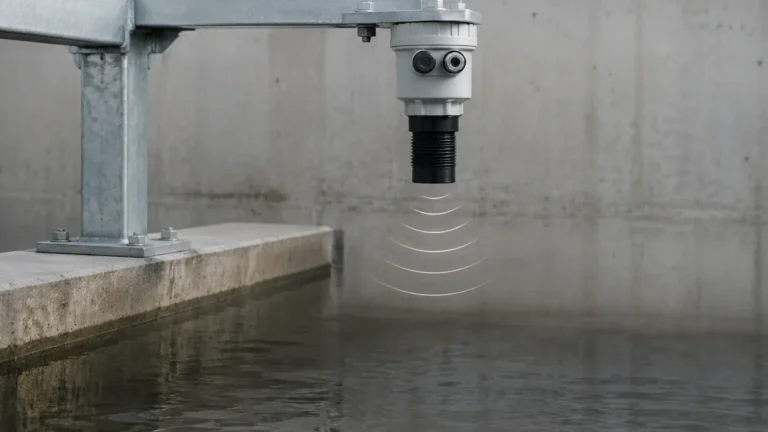
Integrated Ultrasonic Level Meter
Integrated Ultrasonic Level Meter: A Practical Engineering Guide
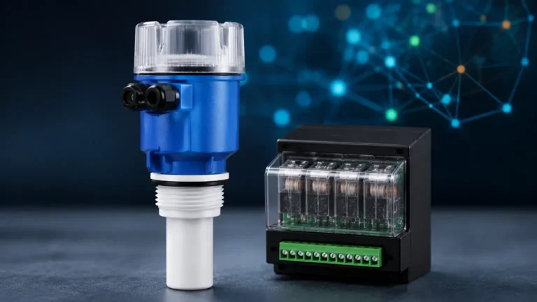
In the landscape of industrial automation and process control, selecting the right instrumentation is critical for operational efficiency and safety. Among the various technologies available for liquid and solid level monitoring, the integrated ultrasonic level meter has emerged as a preferred solution for a wide range of standard applications. By combining the sensor (transducer) and the processing electronics into a single, compact housing, these instruments offer a streamlined approach to level measurement that balances performance with cost-effectiveness.
This guide provides a comprehensive technical overview of Ultrasonic Level Meters, detailing their measurement principles, selection criteria, installation requirements, and practical limitations within industrial environments.
Measurement Principle: The Science of Echo
Before selecting an integrated ultrasonic level meter, it is essential to understand the underlying physics of the technology. Ultrasonic measurement is a non-contact method based on the "Time-of-Flight" (ToF) principle.
The Time-of-Flight (ToF) Calculation
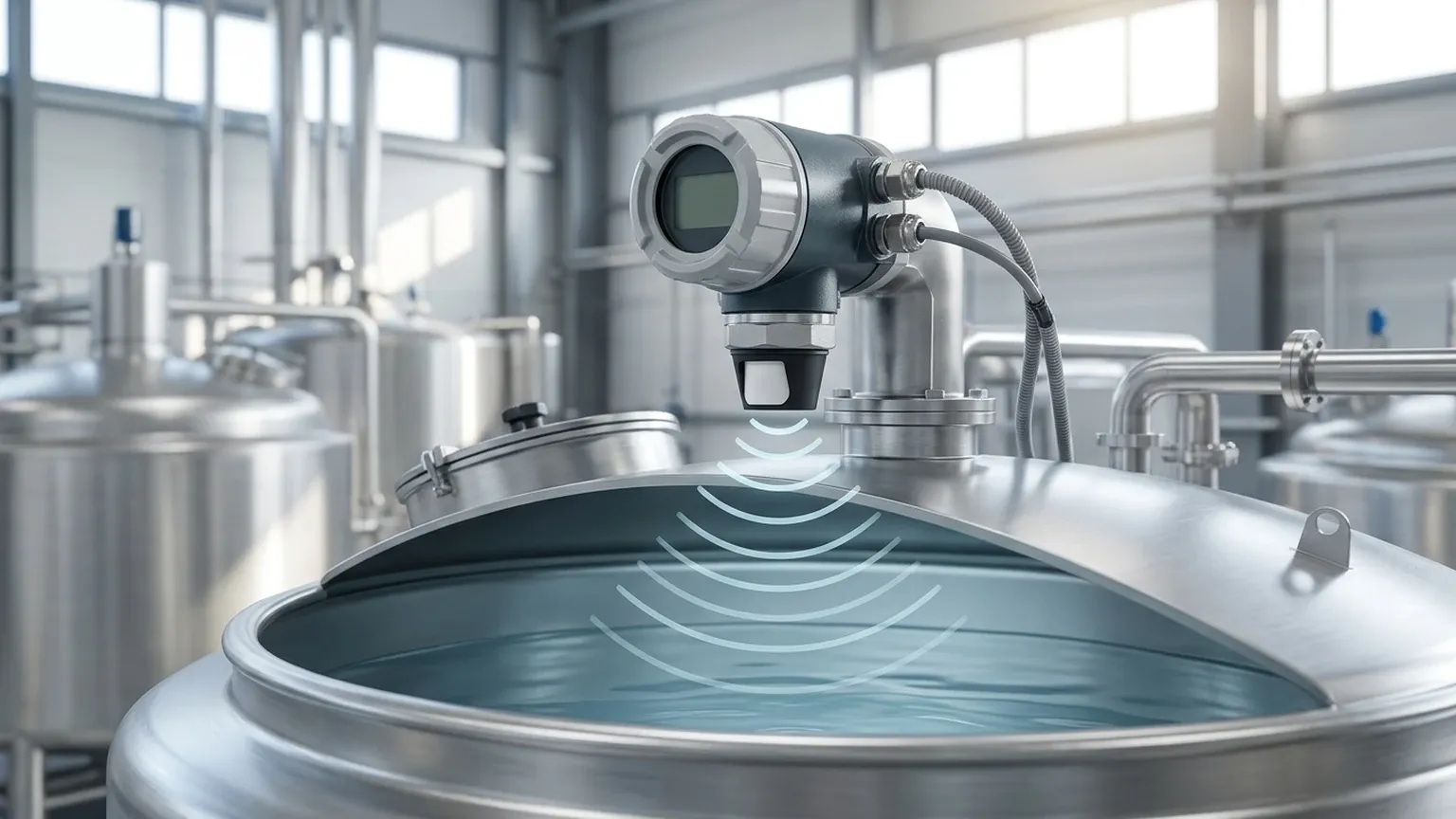
The device's transducer contains a piezoelectric crystal that converts electrical energy into mechanical pulses. These high-frequency sound waves (typically between 20 kHz and 200 kHz) are emitted toward the target medium. When the waves hit the surface of the liquid or solid, they are reflected back toward the sensor. The meter’s internal processor measures the time interval between the emission of the pulse and the reception of the echo.
The distance ($D$) between the sensor and the surface is calculated using the formula:
$$D = \frac{c \times t}{2}$$
Where:
* $c$ is the speed of sound in the medium (typically air).
* $t$ is the total time elapsed for the pulse to travel to the surface and back.
Since the total distance from the sensor to the bottom of the tank ($H$) is known through calibration, the level of the material ($L$) is determined by subtracting the measured distance from the total height ($L = H – D$).
Temperature Compensation
The speed of sound is not constant; it varies significantly with air temperature. For instance, the speed of sound in air increases by approximately 0.6 meters per second for every degree Celsius increase in temperature. To maintain accuracy, high-quality Ultrasonic Level Meters include an integrated temperature sensor to provide real-time compensation for these fluctuations.
The Advantages of the Integrated Design
An integrated ultrasonic level meter differs from "split-type" or remote systems where the transducer and the transmitter/display are separate units connected by a cable. The integrated approach offers several distinct advantages for B2B procurement and engineering projects:
1. Simplified Installation: With only one component to mount and wire, labor costs and installation time are significantly reduced.
2. Reduced Footprint: The compact design is ideal for applications with limited space above the vessel or tank.
3. Lower Total Cost of Ownership: Integrated units generally have lower hardware costs and fewer points of potential failure compared to multi-part systems.
4. Ease of Maintenance: Without external cabling between the sensor and a remote display, troubleshooting is simplified.
Technical Selection Criteria
Choosing the correct integrated ultrasonic level meter requires a detailed analysis of the process conditions. Engineers should evaluate the following parameters before procurement:
1. Measurement Range
Integrated units typically cover ranges from 0.3 meters up to 20 meters. It is vital to select a meter where the maximum range of the application does not exceed 80% of the meter's rated capacity to ensure a strong signal-to-noise ratio in suboptimal conditions.
2. The "Dead Zone" (Blocking Distance)
Every ultrasonic sensor has a minimum distance requirement directly below the transducer face where it cannot accurately measure. This is known as the dead zone or blocking distance. If the liquid level enters this zone, the meter will provide erroneous readings. Standard dead zones range from 0.2m to 0.5m depending on the frequency of the transducer.
3. Beam Angle
The ultrasonic pulse spreads as it travels, forming a cone. The beam angle (typically 5° to 12°) determines the "footprint" of the signal at the target surface. If the beam hits tank walls, ladders, or internal agitators, it will create false echoes.
4. Output and Communication
Standard industrial outputs include 4-20mA (analog) and RS485 (Modbus RTU). Some advanced models also support HART protocol for remote configuration and diagnostics.
Practical Selection Table
The following table outlines typical specifications for standard industrial integrated ultrasonic level meters used in water treatment and chemical storage.
| Feature | Specification (Standard) | Specification (High-Range) |
| :— | :— | :— |
| Measurement Range | 0.4m – 5m | 0.6m – 15m |
| Accuracy | ±0.25% to ±0.5% of Full Scale | ±0.25% to ±0.5% of Full Scale |
| Resolution | 1mm | 3mm |
| Beam Angle | < 10° | < 8° |
| Process Temperature | -20°C to +60°C | -20°C to +70°C |
| Process Pressure | Atmospheric (±0.1 MPa) | Atmospheric (±0.1 MPa) |
| Power Supply | 24V DC / 220V AC | 24V DC |
| Protection Rating | IP66 / IP67 | IP67 / IP68 |
| Output | 4-20mA / RS485 | 4-20mA / RS485 / HART |
Installation Best Practices
To ensure the reliability of an integrated ultrasonic level meter, strict adherence to installation guidelines is required. Improper mounting is the leading cause of measurement failure in ultrasonic systems.
* Vertical Alignment: The transducer face must be perfectly parallel to the liquid surface. A tilt of even a few degrees can cause the reflected signal to miss the receiver.
* Wall Proximity: The sensor should not be mounted too close to the tank wall. A general rule of thumb is to maintain a distance from the wall equal to at least 1/10th of the total tank height.
* Avoid Obstructions: Ensure the path of the ultrasonic beam is clear of inflow pipes, internal bracing, or heating coils. If obstructions are unavoidable, some meters offer "false echo suppression" software to mask these signals.
* Stilling Wells: In applications with heavy surface turbulence or foam, installing the sensor inside a vertical stilling well (a perforated pipe) can help stabilize the reading.
Limitations and Operating Constraints
While highly versatile, the integrated ultrasonic level meter is not a universal solution. Engineers must be aware of specific environmental factors that can attenuate the ultrasonic signal:
1. Heavy Foam: Thick, dense foam acts as an acoustic absorber, preventing the signal from reflecting back to the sensor. In such cases, radar level meters or hydrostatic transmitters may be more appropriate.
2. Vacuum or High Pressure: Ultrasonic waves require a medium (gas/air) to travel. They cannot function in a vacuum. High-pressure environments also alter the speed of sound beyond the compensation capabilities of standard units.
3. Extreme Dust or Vapor: While light dust is manageable, heavy concentrations of airborne particulates or dense steam can scatter the sound waves, leading to signal loss.
4. High Temperature: Most integrated electronics are rated for temperatures below 70°C. For high-temperature reactors, a split-type system or a different technology is required to protect the transmitter electronics.
Common Industry Applications
Welk provides reliable, accurate, and cost-effective level measurement solutions across various sectors using this technology:
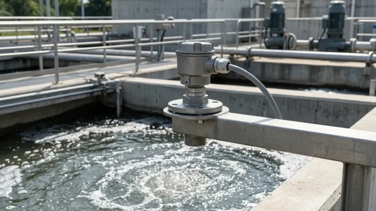
* Water and Wastewater Treatment: Monitoring levels in open channels, sumps, and chemical dosing tanks (e.g., Alum or Chlorine storage).
* Chemical Processing: Level control in atmospheric storage tanks for acids, alkalis, and detergents, provided the materials are compatible with the sensor's wetted parts (often PVDF or PTFE).
* Food and Beverage: Non-contact measurement in clean water storage or ingredient silos where hygiene is a priority.
* Industrial Automation: Integration into PLC/SCADA systems for automated pump control and inventory management.
Frequently Asked Questions (FAQ)
Q: Can an integrated ultrasonic level meter measure solids like grain or sand?
A: Yes, but the range is typically reduced by 50% because solids absorb more sound and reflect it at irregular angles. A model with a higher power output and a lower frequency is usually required for solids.
Q: What maintenance is required for these sensors?
A: Because they are non-contact, maintenance is minimal. However, the transducer face should be checked periodically for condensation or dust buildup, which can be wiped away with a soft cloth.
Q: How does wind affect the measurement in outdoor tanks?
A: Strong wind can "blow" the ultrasonic pulse away or create turbulence in the air, leading to unstable readings. Using a sunshade or a protective shroud can mitigate these effects.
Q: What is the difference between IP67 and IP68 ratings for these meters?
A: IP67 allows for temporary immersion in water, while IP68 indicates the device is suitable for continuous submersion. For most tank-top applications, IP67 is sufficient, but IP68 is recommended for sumps prone to flooding.
Conclusion
The integrated ultrasonic level meter remains a cornerstone of modern industrial level measurement due to its balance of accuracy and simplicity. By understanding the acoustic principles and respecting the physical limitations of the technology, project managers and engineers can implement robust monitoring systems that enhance process safety and efficiency. For specific application support or to explore customized OEM/ODM options, reviewing technical datasheets and consulting with instrumentation experts is the recommended next step in the procurement process.