Bilge Level Switches
Bilge Level Switches
In maritime engineering and industrial sump management, the bilge represents the lowest point of a vessel or structure where excess water, oil, and debris collect. Monitoring these levels is a critical safety requirement to prevent flooding, protect machinery, and ensure environmental compliance. Bilge level switches are specialized point-level detection devices designed to trigger alarms or activate pump systems when liquids reach a predetermined threshold.
Unlike standard tank level sensors, bilge level switches must operate in challenging environments characterized by turbulent fluids, oily mixtures, and suspended solids. This guide examines the fundamental measurement principles, selection criteria, and installation best practices for these essential components.
Measurement Principles of Bilge Level Switches
To select the appropriate instrument, engineers must first understand the physics behind the various detection methods. Bilge environments often contain a mixture of seawater, fresh water, lubricants, and fuel, which can affect the reliability of certain technologies.
Mechanical Float Principles
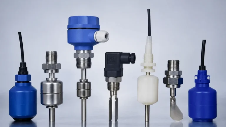
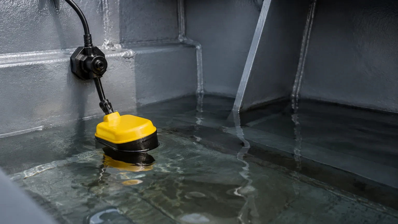
Mechanical float switches are the most common technology used in bilge applications. They operate on the principle of buoyancy. A float, typically made of 316 stainless steel or high-density plastics like Polypropylene (PP) or NBR, contains an internal magnet. As the liquid level rises, the float moves along a stem or pivots on a hinge. When the float reaches a specific height, its magnetic field actuates a hermetically sealed reed switch located within the stationary stem. This completes or breaks an electrical circuit to signal the control system.
Conductive Level Sensing
Conductive switches utilize the electrical conductivity of the liquid to bridge the gap between two or more electrodes. When a conductive liquid (such as seawater or greywater) touches the probes, a low-voltage current flows through the circuit, triggering the switch. While highly reliable for clean water, this principle can fail in bilges where high concentrations of oil or grease may coat the probes, creating an insulating layer that prevents the circuit from closing.
Capacitive Level Sensing
Capacitance switches measure the change in electrical capacitance between a probe and the tank wall (or a reference electrode). As the bilge liquid displaces air around the probe, the dielectric constant changes, altering the capacitance. Modern capacitive Level Switches often include "active shield" technology to ignore buildup or coating on the probe, making them suitable for oily bilge water.
Optical Level Sensing
Optical switches use an infrared LED and a light receiver housed within a glass or plastic prism. When the sensor tip is in air, the infrared light is reflected internally within the prism back to the receiver. When liquid covers the tip, the light is refracted into the liquid, and the receiver detects a drop in light intensity. These are extremely compact but are sensitive to heavy sludge or highly opaque fluids.
Key Selection Criteria for Bilge Environments
Selecting a bilge level switch requires a thorough evaluation of the operational environment. A switch that works in a clean water tank may fail within hours in a heavy industrial bilge.
1. Media Compatibility: The switch materials must resist corrosion from seawater and chemical degradation from fuels and hydraulic oils. 316L Stainless Steel is the industrial standard for durability, while specialized plastics are used for weight reduction or specific chemical resistance.
2. Specific Gravity: For float-based switches, the float must be less dense than the liquid it is intended to measure. Standard bilge water has a specific gravity near 1.0, but heavy oils can lower the overall density of the mixture. Most industrial floats are designed to operate in liquids with a specific gravity as low as 0.6 to 0.8.
3. Ingress Protection (IP Rating): Since bilge switches are frequently submerged or exposed to high-pressure washdowns, an IP68 rating is mandatory. This ensures the internal electronics and switch contacts remain dry under continuous submersion.
4. Vibration and Shock Resistance: In maritime and heavy industrial applications, machinery vibration can cause mechanical fatigue or "chatter" in reed switches. Selecting switches with reinforced stems and dampening features is essential for long-term reliability.
Comparison of Common Bilge Level Switch Technologies
| Technology | Pros | Cons | Best Application |
| :— | :— | :— | :— |
| Magnetic Float | Simple, no power required, low cost. | Moving parts can jam; sensitive to debris. | General-purpose bilge sumps. |
| Conductivity | No moving parts; very durable. | Requires conductive liquid; fails if oily. | Clean water sumps, seawater wells. |
| Capacitance | Solid-state; handles coatings well. | Requires power; more complex calibration. | Oily water separators, hazardous areas. |
| Optical | Very small; fast response. | Sensitive to thick sludge and coating. | Small equipment bilges, leak detection. |
Installation Considerations and Best Practices
Proper installation is as important as the technology itself. Even the highest-quality bilge level switches will fail if positioned incorrectly.
Mounting Orientation
Most bilge switches are designed for either vertical or horizontal mounting. Vertical switches are typically suspended from a bracket or mounted to the floor of the bilge. It is critical to ensure the switch is perfectly vertical (within ±30°) to prevent the float from binding against the stem. Horizontal switches are often used in side-wall applications where overhead space is limited.
Slosh and Turbulence Mitigation
In moving vessels or near pump inlets, the liquid surface is rarely still. This turbulence can cause the switch to cycle rapidly (short-cycling), which can burn out pump motors or create false alarms. To mitigate this, engineers should:
* Use a Stilling Well: A perforated pipe (usually 50mm to 100mm in diameter) surrounding the switch to dampen surface movement.
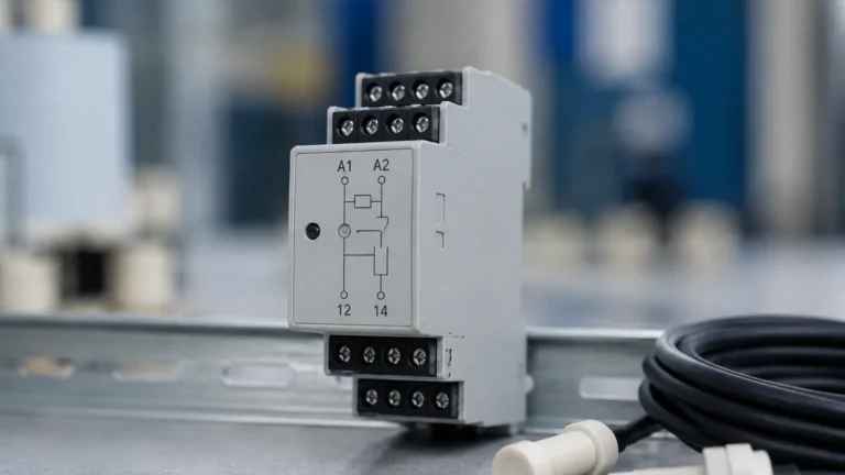
* Implement Time Delays: Use a control relay with a 5–10 second delay to ensure the switch state is stable before activating equipment.
Wiring and Junctions
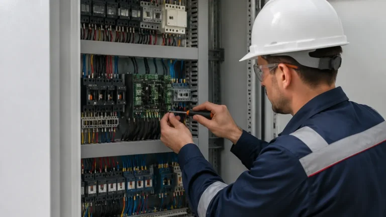
Bilge environments are corrosive. All wiring should be marine-grade, tinned copper to prevent "wicking" of moisture. Junction boxes must be located well above the maximum possible flood level. If a submerged cable entry is necessary, use epoxy-sealed cable glands to maintain the IP68 integrity of the switch housing.
Operational Limitations and Common Risks
Despite their robust design, bilge level switches face several operational risks that must be managed through regular maintenance and proper system design.
* Fouling and Debris: Bilges often contain rags, wood chips, and metal shavings. These can physically wedge a float in the "down" position, preventing an alarm during a flood, or in the "up" position, causing a pump to run dry. Protective cages or slosh shields are highly recommended to keep large debris away from the moving parts.
* Coating and Scaling: In industrial sumps, minerals or oils can form a hard scale or a thick film on the sensor. For capacitive and conductive sensors, this can lead to false positives. Regular inspection and cleaning (typically every 3–6 months) are necessary.
* Magnetic Interference: For magnetic reed switches, the presence of large ferrous objects or strong electromagnetic fields from nearby motors can theoretically interfere with the switch operation, though this is rare in modern shielded designs.
Frequently Asked Questions (FAQs)
Q: Can I use a bilge level switch for both high-level alarm and pump control?
A: Yes, but it is often better to use two separate switches or a single switch with two independent float points. This provides redundancy and allows for a "hysteresis" zone (e.g., pump starts at 300mm and stops at 100mm) to prevent excessive pump cycling.
Q: What is the difference between a N.O. and N.C. switch configuration in a bilge?
A: A Normally Open (N.O.) switch closes the circuit when the liquid rises, typically used for alarms. A Normally Closed (N.C.) switch opens the circuit when the liquid rises. For safety-critical applications, N.C. is often preferred for high-level alarms because if a wire breaks, the system will trigger a "fail-safe" alarm.
Q: How do I test a bilge switch without flooding the compartment?
A: Most high-quality industrial switches include a manual test lever or a magnetic test point that allows the operator to lift the float or simulate a high-level state manually during routine inspections.
Conclusion
Bilge level switches are a fundamental component of industrial and maritime safety. By understanding the specific requirements of the bilge environment—including the presence of oils, debris, and turbulence—engineers can select a technology that provides reliable, long-term performance. Whether utilizing the simplicity of a magnetic float or the advanced capabilities of capacitive sensing, proper installation and regular maintenance remain the keys to preventing costly flooding incidents and environmental non-compliance. For more technical specifications on industrial-grade measurement solutions, review the available options for Level Switches to find the right fit for your specific application.