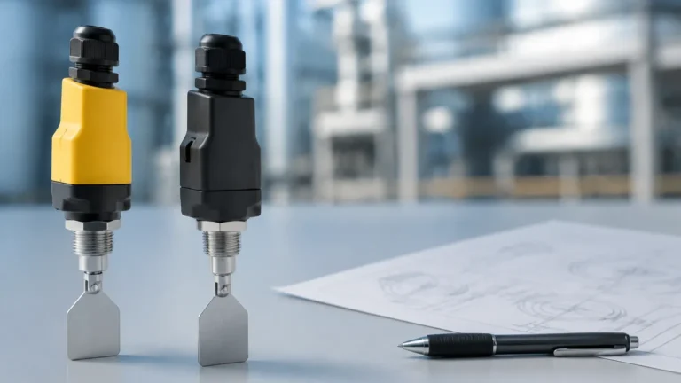
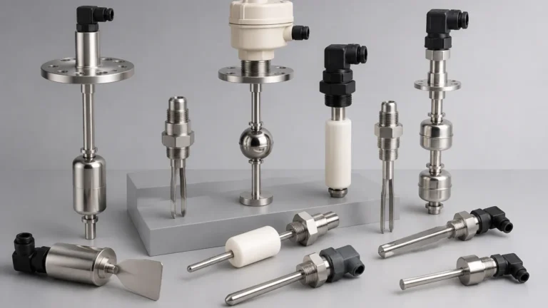
Boiler Level Switches
Boiler Level Switches
In industrial steam generation and hot water systems, the precise monitoring of liquid levels is a critical safety and operational requirement. Boiler level switches serve as the primary line of defense against catastrophic failures, such as dry-firing or water carryover into steam turbines. These devices are designed to operate under extreme conditions, including high saturated steam temperatures and significant pressures, where standard level sensors might fail.
This guide examines the engineering principles, selection criteria, and installation requirements for industrial Level Switches specifically configured for boiler environments. Understanding the nuances of these instruments is essential for plant engineers and maintenance professionals tasked with ensuring system reliability and regulatory compliance.
Measurement Principles for Boiler Level Control
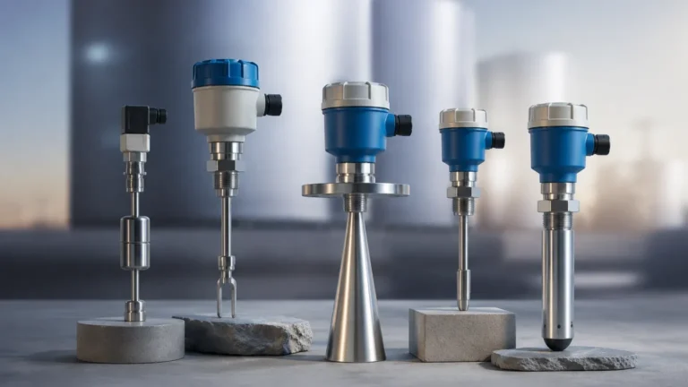
Boiler environments present unique challenges due to the coexistence of liquid water and saturated steam. The physical properties of the medium change significantly with temperature and pressure, influencing how different sensing technologies perform. The most common principles used in boiler level switches include conductivity, buoyancy (float/displacer), and capacitance.
Conductivity Probes
Conductivity level switches utilize the electrical conductivity of boiler water to complete a circuit. A low-voltage AC signal is applied to a stainless steel probe. When the water level rises and touches the probe, the circuit is completed through the water to the boiler shell (or a reference electrode), triggering a relay.
Because steam is non-conductive, this method provides a very sharp and reliable point-level detection. In modern boilers, multi-probe systems are often used to provide high-level alarms, low-level alarms, and the critical Low Water Fuel Cutoff (LWCO) function. These systems are favored for their lack of moving parts, making them resistant to mechanical wear in high-vibration environments.
Buoyancy-Based Switches (Float and Displacer)
Buoyancy remains one of the most traditional methods for boiler level detection.
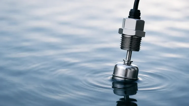
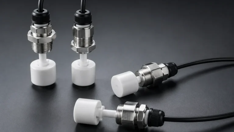
1. Magnetic Float Switches: A float containing a permanent magnet moves with the water level. As it reaches a set point, the magnetic field actuates a reed switch or a microswitch located outside the pressure boundary. This isolation ensures that the electrical components are not exposed to the process heat.
2. Displacer Switches: Unlike floats that ride on the surface, displacers are heavier than the liquid and are suspended by a spring. As the liquid rises, the apparent weight of the displacer decreases (Archimedes' principle), causing the spring to retract and actuate a switch. Displacers are particularly effective in high-pressure boilers where the density difference between water and steam narrows.
Capacitance Level Switches
Capacitance sensors measure the change in electrical capacitance between a probe and the vessel wall. Since water has a much higher dielectric constant (approximately 80) than steam (approximately 1), the capacitance increases significantly as the probe is submerged. These switches are often used in high-pressure applications where mechanical floats might be crushed or where conductivity is too low for probe-style sensors.
Technical Selection Criteria for Boiler Level Switches
Selecting the correct instrument requires a thorough analysis of the boiler’s operating parameters. Standard industrial switches are rarely suitable; specialized boiler level switches must be rated for the specific thermodynamic conditions of steam systems.
Temperature and Pressure Ratings
Boilers operate on the saturated steam curve. A switch rated for 10 bar (145 psi) must also be able to withstand the corresponding saturation temperature of 184°C (363°F). It is standard practice to select instruments with a safety margin of at least 20% above the maximum allowable working pressure (MAWP) of the boiler.
Material Compatibility
Boiler water is often chemically treated to prevent scale and corrosion. Common materials for wetted parts include 316L stainless steel, Monel, or Hastelloy. For conductivity probes, the insulation material (typically PTFE or ceramics) must be capable of resisting long-term exposure to high-temperature steam without degrading or "tracking" (forming a conductive path on the insulator surface).
Comparison of Level Switch Technologies
| Technology | Max Temperature (Typical) | Max Pressure (Typical) | Best Use Case | Limitations |
| :— | :— | :— | :— | :— |
| Conductivity | Up to 370°C (698°F) | Up to 200 bar (2900 psi) | High/Low alarms, LWCO | Requires conductive liquid (>0.5 μS/cm) |
| Magnetic Float | Up to 250°C (482°F) | Up to 40 bar (580 psi) | General purpose, simple control | Moving parts can stick if scaled |
| Displacer | Up to 400°C (752°F) | Up to 100 bar (1450 psi) | High pressure, turbulent tanks | Large footprint required |
| Capacitance | Up to 200°C (392°F) | Up to 64 bar (928 psi) | Non-conductive fluids, coating | Sensitive to dielectric changes |
Installation and Engineering Considerations
Correct installation is as vital as the technology selection itself. Improperly mounted switches can lead to "nuisance tripping" or, worse, a failure to act during a low-water event.
External Chambers and Stilling Wells
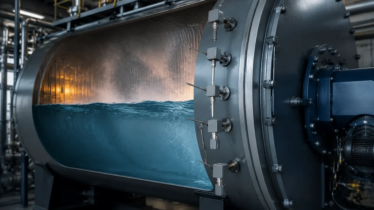
To protect the switch from the turbulence of the boiling process and the influence of steam bubbles, level switches are often mounted in external bypass chambers or internal stilling wells.
* Bypass Chambers: These are mounted on the side of the boiler drum. They provide a stable environment for the float or probe and allow for maintenance (via isolation valves) without blowing down the entire boiler.
* Steam and Water Connections: The top connection must go to the steam space, and the bottom connection must go to the water space. These lines must be clear of obstructions and properly sloped to prevent condensate trapping.
Wiring and Safety Interlocks
In many jurisdictions, the Low Water Fuel Cutoff (LWCO) is a legal requirement governed by standards such as ASME CSD-1 or the PED (Pressure Equipment Directive). These switches must be wired in a "normally closed" configuration, meaning the circuit opens to shut down the burner if the water level drops or if power is lost (fail-safe design).
Redundancy and Diversity
Critical high-pressure boilers often employ the principle of redundancy (using two switches for the same function) and diversity (using two different technologies, such as one conductivity probe and one float switch) to eliminate common-mode failures.
Limitations and Operational Risks
While robust, boiler level switches are subject to several environmental risks that can compromise accuracy:
1. Scaling and Fouling: High mineral content in boiler water can lead to scale buildup on floats or conductivity probes. Scale on a float can increase its weight, causing it to sink and trigger a false low-level alarm. Scale on a probe can act as an insulator, preventing the switch from detecting water.
2. Foaming: Over-treatment with chemicals or high levels of dissolved solids can cause foaming. A level switch may detect the foam as liquid, leading to a dangerously low actual water level while the switch indicates "normal."
3. Specific Gravity Changes: As water temperature increases, its density decreases. A float designed for water at 20°C (0.998 g/cm³) may sit lower in water at 200°C (0.865 g/cm³). Selection must account for the specific gravity at operating temperature.
Frequently Asked Questions (FAQ)
Q: How often should boiler level switches be tested?
A: Most safety standards require a "daily blowdown" or weekly functional test of the LWCO. This involves manually lowering the water level (or simulating it) to ensure the burner actually cuts out. This prevents the mechanism from seizing due to sediment buildup.
Q: Can I use a standard ultrasonic level switch on a boiler?
A: Generally, no. Standard ultrasonic switches struggle with the high-pressure steam environment, as the speed of sound changes with steam density and temperature, and the heavy condensation on the sensor face can block the signal.
Q: What is the difference between a level switch and a level transmitter in a boiler?
A: A level switch provides a discrete on/off signal at a specific point (e.g., "water is too low"). A level transmitter provides a continuous signal (e.g., 4-20mA) representing the exact level (e.g., "water is at 45%"). Boilers typically use transmitters for modulating feed-water control and switches for emergency safety shutdowns.
Q: Why do conductivity probes use AC instead of DC?
A: AC is used to prevent electrolysis. If DC were used, the constant current flow would cause ions to migrate, leading to rapid corrosion of the probe and the buildup of plating, which would eventually cause the sensor to fail.
Conclusion
Boiler level switches are indispensable components in the safe operation of steam-generating plant equipment. By understanding the underlying physics of conductivity and buoyancy, and by adhering to strict installation and maintenance protocols, engineers can significantly reduce the risk of boiler accidents. When evaluating options for Level Switches, always prioritize instruments that meet the specific pressure and temperature ratings of your vessel and ensure they are integrated into a comprehensive safety instrumented system (SIS).