Level Switch Displacer Type
Level Switch Displacer Type
In the landscape of industrial automation and process control, point-level detection serves as a critical safeguard for preventing tank overfills, protecting pumps from dry running, and managing complex liquid-liquid interfaces. Among the various technologies available, the level switch displacer type remains a cornerstone for high-pressure, high-temperature, and heavy-duty industrial applications. Unlike standard float switches that rely on buoyancy to stay on the surface of a liquid, displacer-type instruments operate on the principle of weight displacement, offering distinct advantages in stability and adjustability.
Understanding the Measurement Principle
The operation of a level switch displacer type is rooted in Archimedes' Principle, which states that a body immersed in a fluid is buoyed up by a force equal to the weight of the fluid displaced by the body. However, there is a fundamental mechanical difference between a float and a displacer.
Buoyancy vs. Weight
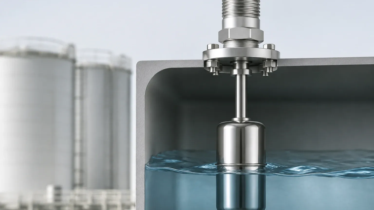
A float is designed to be lighter than the process liquid, allowing it to ride on the surface. In contrast, a displacer is intentionally designed to be heavier than the liquid. It is suspended from a spring or a torque tube mechanism. In a dry state, the full weight of the displacer exerts a downward force on the sensing element. As the liquid level rises and covers the displacer, the buoyant force acts upward, effectively reducing the "apparent weight" of the displacer.
Mechanical Actuation
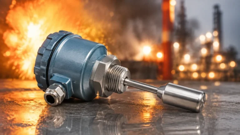
This change in apparent weight causes a slight upward movement of the suspension spring or a rotation in a torque tube. This mechanical shift is typically transmitted through a non-magnetic pressure tube to an external switch mechanism. Most modern designs utilize a magnetic sleeve attached to the displacer rod. When the sleeve moves into the field of an externally mounted magnet, it actuates a microswitch or a pneumatic valve. Because the switching components are isolated from the process media by the pressure tube, the level switch displacer type is exceptionally well-suited for hazardous or corrosive environments.
Key Components and Design Variations
To select the correct instrument, engineers must understand the modular nature of these switches. A standard setup usually consists of three primary elements:
1. The Displacer: A solid or hollow cylinder, often made of Stainless Steel (316L), Monel, or Hastelloy, depending on the chemical compatibility of the fluid.
2. The Suspension Element: A range-spring or a torque tube that translates weight changes into motion.
3. The Switch Housing: Contains the electrical or pneumatic switching elements, often rated for explosion-proof (ATEX/IECEx) environments.
Single-Stage vs. Multi-Stage Switches
One of the primary benefits of the displacer design is the ability to monitor multiple levels with a single tank entry.
* Single-Stage: Triggers one alarm point (e.g., High Level).
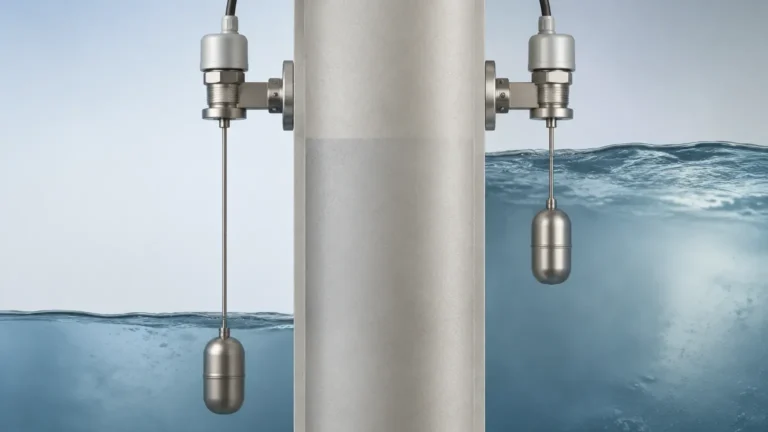
* Multi-Stage: Uses multiple displacers suspended at different heights on a single cable or rod. This allows a single unit to provide Low-Low, Low, High, and High-High level alerts, significantly reducing installation costs and vessel penetrations.
Practical Selection Criteria
When evaluating Level Switches for a specific project, the displacer type should be compared against other technologies based on the process conditions. The following table provides a comparison for engineering decision-making:
| Feature | Displacer Type | Float Switch | Ultrasonic (Point) | Tuning Fork |
| :— | :— | :— | :— | :— |
| Pressure Range | Up to 345 bar (5000 psi) | Moderate | Atmospheric | Up to 64 bar |
| Temp. Range | -196°C to +540°C | Up to 250°C | Up to 150°C | Up to 280°C |
| Specific Gravity | Sensitive (Adjustable) | Critical (Fixed) | Not Applicable | Minimal Impact |
| Interface Detection | Excellent | Possible | Poor | Limited |
| Turbulence | High Resistance | Low Resistance | Moderate | High Resistance |
| Maintenance | Low (Mechanical) | Moderate | Low (Electronic) | Low (Electronic) |
Specific Gravity Considerations
Because the displacer relies on the weight of the displaced fluid, the specific gravity (SG) of the liquid is the most critical factor in calibration. If a switch is calibrated for water (SG 1.0) but used in a light hydrocarbon (SG 0.6), the buoyant force will be insufficient to actuate the switch at the intended point. Most industrial displacers can be field-adjusted to accommodate changes in fluid density by moving the displacer position on the cable or adjusting the spring tension.
Installation Considerations and Best Practices
Proper installation is paramount to ensuring the longevity and accuracy of a level switch displacer type. Engineers should adhere to the following guidelines:
1. Stilling Wells and Cages: In vessels with high turbulence or agitation, the displacer should be installed inside a stilling well or an external chamber (cage). This prevents the displacer from swinging, which could cause premature mechanical wear or false alarms.
2. Vertical Alignment: The unit must be mounted perfectly vertical. Any tilt can cause the displacer or the magnetic sleeve to rub against the side of the pressure tube, leading to friction and eventual failure.
3. Clearance: Ensure there is adequate clearance between the bottom of the displacer and the bottom of the tank or chamber. Accumulated sediment or sludge can trap the displacer, preventing it from sensing weight changes.
4. Venting and Draining: For external cage installations, ensure the cage is equipped with vent and drain valves. This allows for easy calibration checks and maintenance without shutting down the entire process line.
Limitations and Common Risks
While robust, the level switch displacer type is not a universal solution. Engineers must be aware of the following limitations:
* Media Buildup: In applications involving heavy crude oil, paraffin, or crystallizing chemicals, material can coat the displacer. This increases its physical weight and changes its volume, leading to significant set-point drift.
* Density Fluctuations: If the process involves fluids with widely varying densities (e.g., batch processing different chemicals), the switch may require frequent recalibration.
* Mechanical Fatigue: In extremely high-cycle applications, the internal spring can suffer from fatigue over several years. Periodic proof-testing is recommended in safety-instrumented systems (SIS).
Frequently Asked Questions (FAQs)
Q: Can a displacer switch be used for liquid-liquid interface detection?
A: Yes. By selecting a displacer with a weight that is between the weights of the two displaced liquids, the switch can accurately detect the interface between, for example, oil and water. The displacer will sink through the upper liquid but "float" (experience enough buoyancy) when it hits the heavier lower liquid.
Q: What is the difference between a top-mounted and side-mounted displacer?
A: Top-mounted units are suspended directly into the main vessel. Side-mounted units are typically housed in an external metal chamber (cage) connected to the vessel via piping. Side-mounted versions are preferred for maintenance because they can be isolated from the vessel with valves.
Q: How do I test the switch without changing the tank level?
A: Many high-quality displacer switches include a "test lifting lever." This allows a technician to manually lift the displacer rod/sleeve to simulate a high-level condition, verifying the electrical integrity of the alarm circuit without needing to fill the tank.
Q: Are displacer switches affected by foam?
A: Generally, no. Because the foam has very low density, it does not provide enough buoyant force to move the heavy displacer. This makes the displacer type superior to ultrasonic or radar sensors in applications where thick foam layers are present.
Technical Confirmation for Project Planning
Before finalizing the specification for a level switch displacer type, project teams should confirm the following data points with the manufacturer:
* Minimum and Maximum Operating Pressure: Ensure the housing and flange ratings exceed process safety margins.
* Fluid Density (Specific Gravity): Provide the minimum SG at the operating temperature.
* Materials of Construction: Verify that the displacer, cable/rod, and gaskets are compatible with the process media (e.g., H2S presence in oil and gas).
* Switching Requirements: Determine if DPDT (Double Pole Double Throw) or SPDT (Single Pole Double Throw) contacts are required for the control logic.
In conclusion, the level switch displacer type remains a highly reliable and versatile tool for industrial level control. By understanding the underlying physics of displacement and adhering to strict installation standards, facilities can achieve precise point-level detection even in the most demanding process environments. For those seeking durable and high-precision instrumentation, exploring the full range of Level Switches is an essential step in optimizing plant safety and operational efficiency.